
Flying apparatus

Inactive Publication Date: 2010-01-21
MOORE W ERIC
View PDF18 Cites 2 Cited by
  • Summary
  • Abstract
  • Description
  • Claims
  • Application Information

AI Technical Summary

Benefits of technology

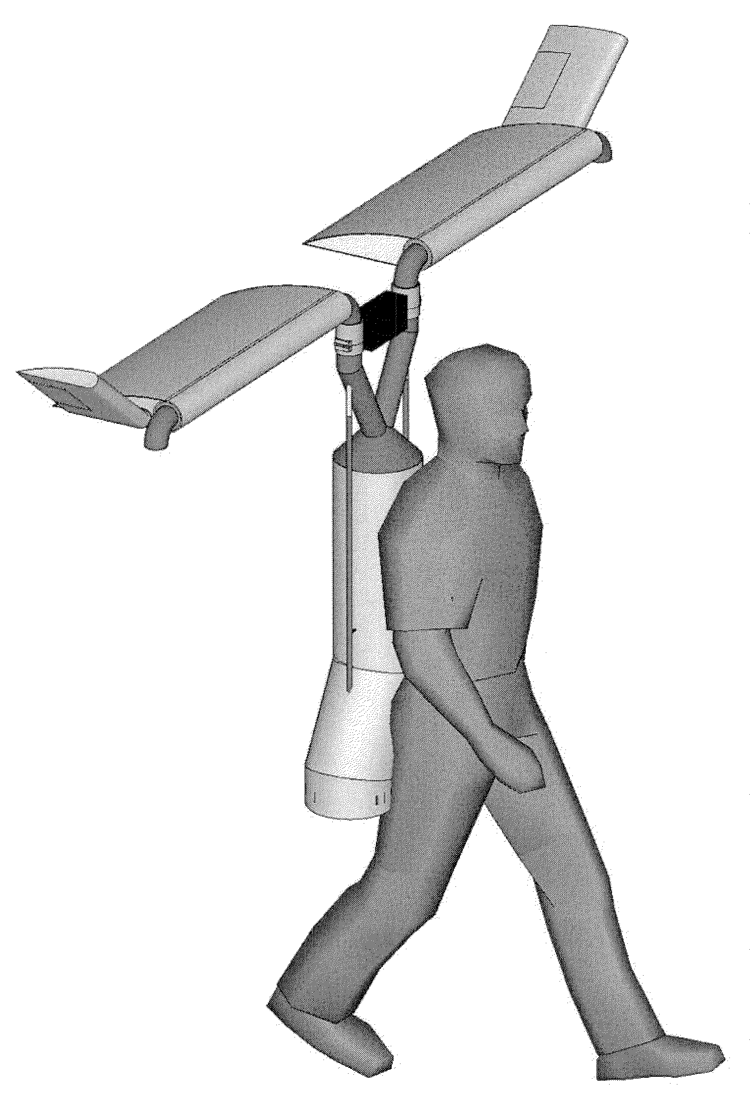
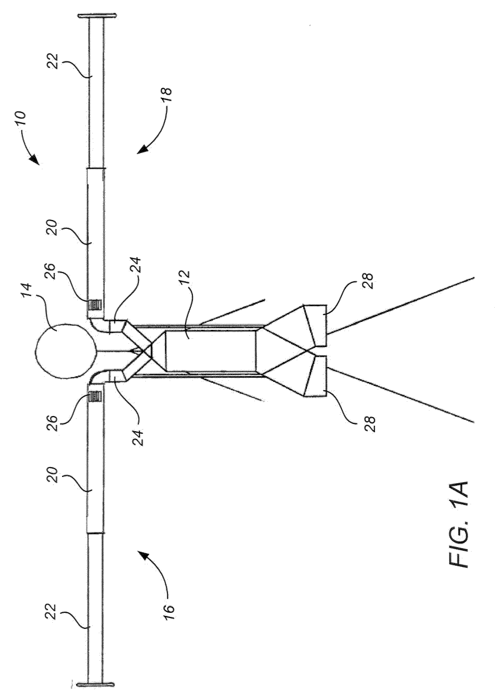
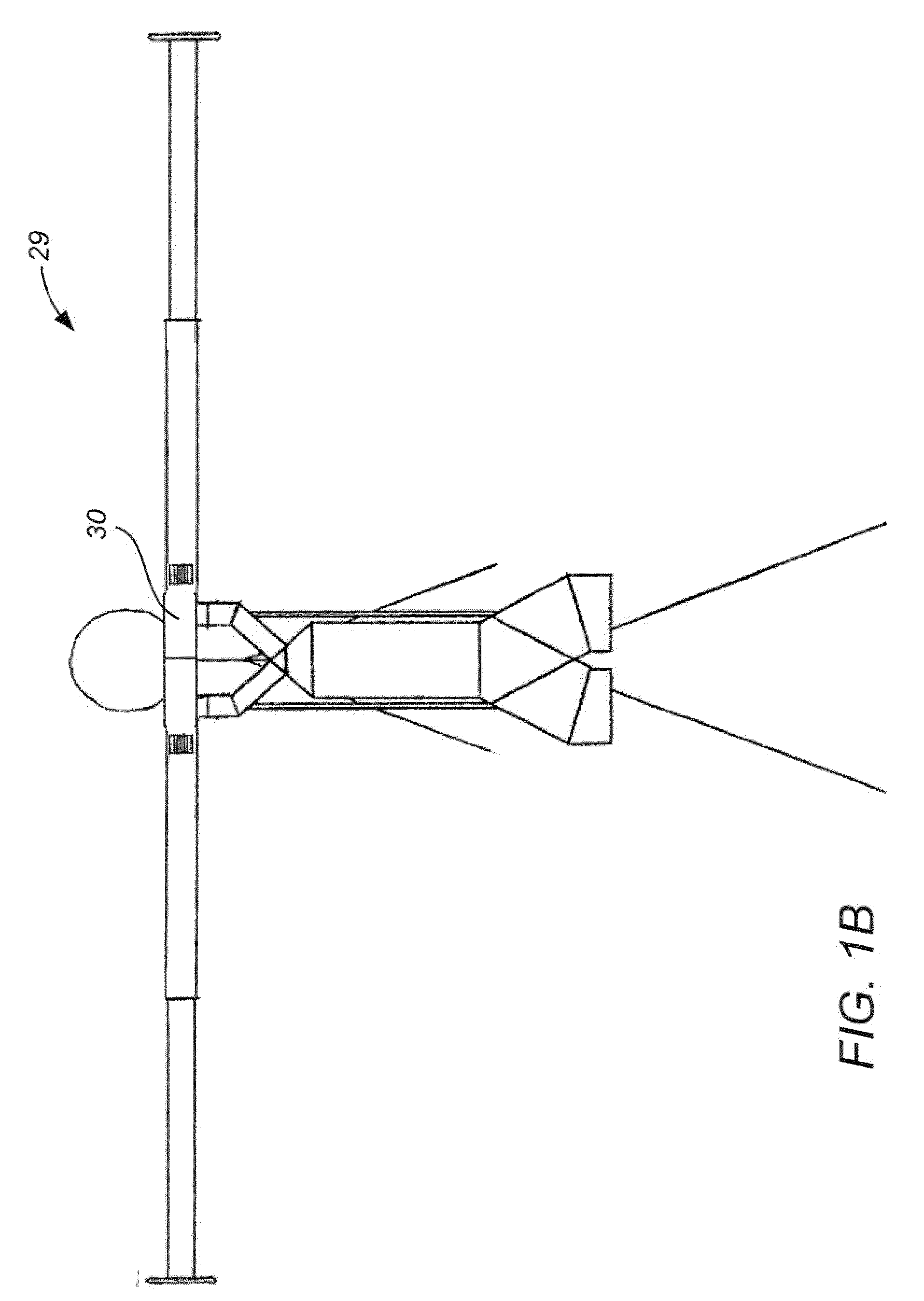
[0005]The present disclosure provides improved short or vertical takeoff and landing flying apparatus. In many embodiments, a flying apparatus incorporates a thrust directing wing for selective redirection of a thrust flow generated by a thrust flow generator. In many embodiments, the thrust flow generator includes a gas turbine engine. In many embodiments, the gas turbine engine includes two rotating shafts with each rotating shaft coupling a compressor with a turbine. In many embodiments, a vertical takeoff and landing flying apparatus configured with a wing provides a forward flight mode during which the wing generates lift, thereby increasing the lift to drag ratio and decreasing the amount of thrust required. A decrease in required thrust level may provide for increased maximum flight time and associated range. A thrust directing wing provides a means for flight control, including the ability to transition between vertical takeoff, forward flight, and vertical landing. A vertical takeoff and landing personal flying apparatus configured with a thrust redirecting wing may provide increased maximum flight time and range as compared to jet packs and the like that rely entirely on engine thrust to maintain lift. A gas turbine engine with two rotating shafts may provide increased damage tolerance, and can be used to generate two separate thrust flows that can be supplied to opposite wing sections.

Problems solved by technology

While there are a wide range of air travel choices available today, existing options suffer from significant disadvantages for individuals traveling by air, particularly in terms of their convenience and affordability.
Recently, enhanced security measures at airports established to combat possible terrorism has unfortunately resulted in increased inconvenience for air travelers.
Existing private or individual air travel options suffer from a variety of limitations.
For example, while personal jet packs provide vertical takeoff and landing capability for demonstrations, air shows, sporting events and the like, their relatively short maximum flight times (typically less than 1 minute) and range limit their use.

Method used


Image

  • Flying apparatus
  • Flying apparatus
  • Flying apparatus

Examples


Embodiment Construction

[0044]The present disclosure provides vertical takeoff and landing flying apparatus. In many embodiments, a personal flying apparatus is provided for use by a single human operator for individual human flight. Alternative embodiments and / or aspects may be employed for unmanned vehicles, for transporting cargo, for Short take-off and / or Landing aircraft, and / or the like. In many embodiments, a flying apparatus includes a thrust directing wing for the selective redirection of a thrust flow received from a thrust flow generator. In many embodiments, a wing provides lift during forward flight. Selective redirection of thrust flow can be used to selectively generate vertical thrust, forward thrust, and combinations thereof, thereby providing the ability to transition between a vertical takeoff and landing mode, a forward flight mode, and combinations thereof.

[0045]The present disclosure provides a range of example variations of vertical takeoff and landing flying apparatus. For example, ...


PUM


Abstract

A flying apparatus having a thrust directing wing is disclosed. The flying apparatus can include a wing that receives a thrust flow from a thrust flow generator, and selectively redirect the flow in at least one of a plurality of directions. The wing can redirect the thrust flow so as to generate vertical thrust, forward thrust, and combinations thereof. The thrust flow generator can include a gas turbine engine, which can include two rotating shafts and a common burner, with each shaft coupling a compressor with a turbine.

Description

CROSS-REFERENCE TO RELATED APPLICATION[0001]The present invention claims the benefit of priority under 35 U.S.C. §119(e) of U.S. Provisional Application No. 61 / 081,670, filed Jul. 17, 2008 (Attorney Docket No. 027492-000100US), the entire content of which is incorporated herein by reference.BACKGROUND[0002]The present disclosure relates generally to the field of aircraft and other flying devices and systems, and more particularly, to an improved vertical takeoff and landing flying apparatus, optionally for use by an individual operator.[0003]Powered flight is a ubiquitous part of modern life. The development of air travel has enabled millions to conveniently travel great distances in a timely and affordable manner. Various types of aircraft, from small private planes to large commercial aircraft, provide an extensive range of choice to the modern day air traveler. Where space for takeoff and landing is constrained, helicopters can be used.[0004]While there are a wide range of air tr...

Claims


Application Information

Patent Timeline
IPC IPC(8): B64C29/00
CPCB64C39/026F02K3/077F02K3/04
Inventor MOORE, W. ERIC
Owner MOORE W ERIC
Learn More