
Combined electrochemical and laser micromaching process for creating ultri-thin surfaces

Inactive Publication Date: 2010-01-21
BANG & OLUFSEN
View PDF2 Cites 7 Cited by
  • Summary
  • Abstract
  • Description
  • Claims
  • Application Information

AI Technical Summary

Benefits of technology

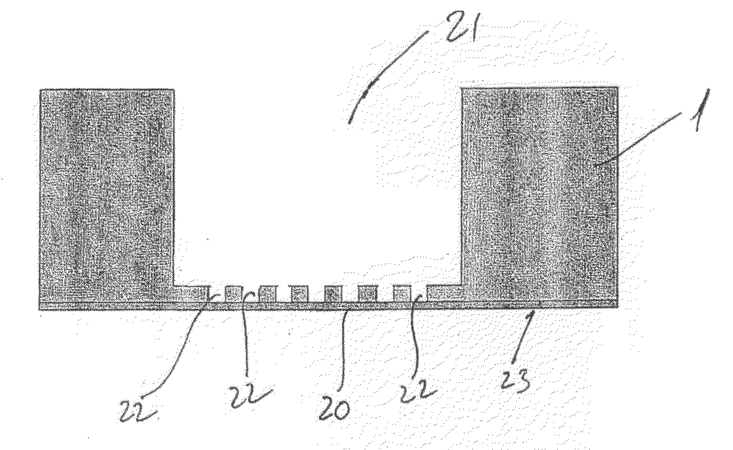
[0008]By combining the two methods it is possible by the electrochemical process quickly to remove a substantial amount of material. The electrochemical process is not as precise and accurate so that it may be possible to solely rely on and use this method in order to create the ultra-thin sections or translucent sections. However, by removing material by an electrochemical process down to a thickness of approx. 10-12 micrometres, enough margin is provided, so that the electrochemical process may be controlled in a manner so that it is satisfied that there is a material thickness left at the bottom of this first cavity. By thereafter applying the laser technique, in a laser micromachining process, the remaining material down to a predetermined level, e.g. 1-5 micrometres, may be achieved relatively rapidly, so that a relatively quick process for the manufacture of these ultra-thin sections in an electrically conducting material is achieved.
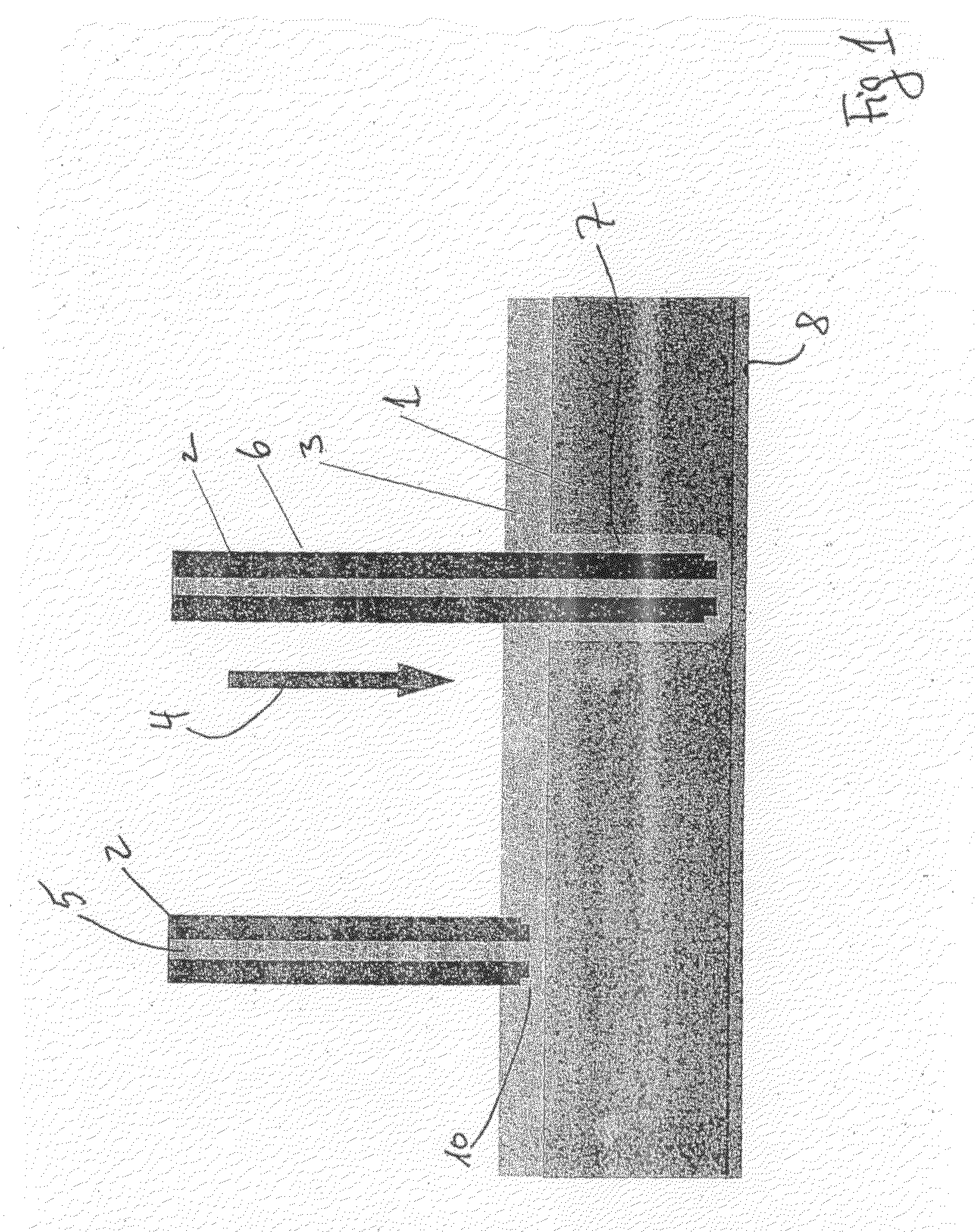
[0013]The tool, i.e. the anode, in an example has a distal end with a diameter of approx. 1 millimetre. This in turn creates holes in the electrically conducting material in the range from 1.5 millimetres to 2.5 millimetres in diameter, where the variation is caused by the voltage of the current, the current density and the electrolyte. Therefore, by keeping the distance between the anode and the cathode constant, i.e. having a continuous feed of anode into the hole in the material, a substantially continuous and relatively fast process is achieved.
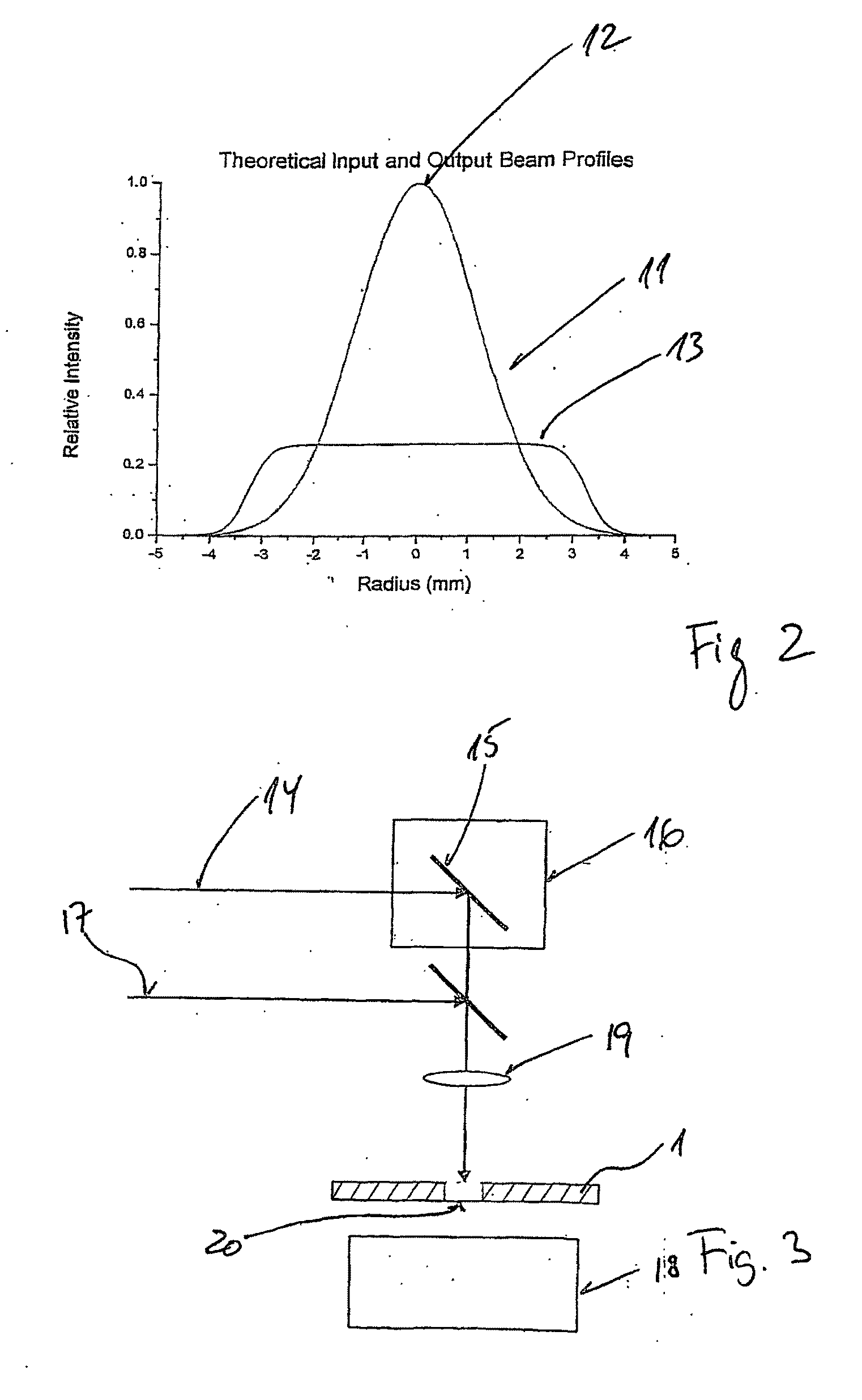
[0022]When using laser-beams and in particular when the laser-beams have been reshaped, a trepanning or percussion mode of the laser-beam has been found to be advantageous in that it is well-defined how much material is removed by each pulse of laser and thereby it becomes possible to very accurately guide and control the laser beam in order to create the cavity having an ultra-thin section left at the bottom of the hole.

Problems solved by technology

This process, however, was very efficient in creating the grids of dots which together formed the symbols on the front side of panels produced by this method, but the production method was extremely time-consuming in that the laser process, although being very precise, is extremely time-consuming.

Method used


Image

  • Combined electrochemical and laser micromaching process for creating ultri-thin surfaces
  • Combined electrochemical and laser micromaching process for creating ultri-thin surfaces
  • Combined electrochemical and laser micromaching process for creating ultri-thin surfaces

Examples


Embodiment Construction

[0005]The invention addresses this problem by providing a process for the manufacture of ultra-thin sections in an electrically conducting material, comprising:[0006]firstly removing material in an electrochemical process to a material thickness of approximately 10 to 20 micrometers;[0007]secondly removing further material by a laser micromachining process to a material thickness of 1 to 5 micrometers.

[0008]By combining the two methods it is possible by the electrochemical process quickly to remove a substantial amount of material. The electrochemical process is not as precise and accurate so that it may be possible to solely rely on and use this method in order to create the ultra-thin sections or translucent sections. However, by removing material by an electrochemical process down to a thickness of approx. 10-12 micrometres, enough margin is provided, so that the electrochemical process may be controlled in a manner so that it is satisfied that there is a material thickness left ...


PUM

PropertyMeasurementUnit
Lengthaaaaaaaaaa
Timeaaaaaaaaaa
Timeaaaaaaaaaa

Abstract

Ultra-thin sections in an electrically conducting material are formed by electrochemically removing material to a thickness of approximately 5 to 150 micrometers and removing further material by laser micromachining to a material thickness of 1 to 30 micrometers. The electrochemical process quickly removes substantial material but is not as precise and accurate as laser machining to create the ultra-thin sections or translucent sections. Removing material by an electrochemical process may be controlled down to a thickness of approx. 10-12 micrometres so that enough margin of a material thickness is left at the bottom of this first cavity. The laser micromachining process removes remaining material down to a predetermined level, e.g. 1-5 micrometres, relatively rapidly, so that a relatively quick process for the manufacture of ultra-thin sections in an electrically conducting material is achieved. A metal structure manufactured by the novel and inventive process is disclosed.

Description

FIELD OF THE INVENTION [0001]The present invention relates to a process for the manufacture of ultra-thin sections in an electrically conducting material.BACKGROUND OF THE INVENTION [0002]In the art it has been suggested and in particular by the same applicants prior patent application published under WO 2004 / 077388 to create a plate where one surface, i.e. the user's interface appears to be without markings whereas on the backside apertures (blind holes) are provided so that it is possible to shine light through these apertures whereby the front side of the panel will indicate symbols or areas where interaction with the display unit may be carried out. The prior art document further describes a process for the manufacture wherein a UV-excimer femtosecond laser was used in order to create a number of dots approximately one millimetre by one millimetre in area where the translucency in the bottom of the cavities, i.e. in each thin section was 0.1 percent.[0003]This process, however, ...

Claims


Application Information

Patent Timeline
IPC IPC(8): C25F3/02
CPCB23H5/06B23K26/4005B23K26/421B23K26/4095B23K26/402B23K26/40B23K26/60B23K2101/35B23K2103/50
Inventor PRICHYSTAL, JAN PHUKLIN
Owner BANG & OLUFSEN
Learn More