
Intermediate member for laser bonding and method of bonding using the same

a laser bonding and intermediate member technology, applied in the field of intermediate members, can solve the problems of insufficient strength and reliability, inability to absorb the local volumetric change of resin, and limit the combination of bondable materials, etc., and achieve the effect of simple and easy operation and high bonding strength

Inactive Publication Date: 2010-01-14
OKAYAMA PREFECTURAL GOVERNMENT +1
View PDF11 Cites 17 Cited by
  • Summary
  • Abstract
  • Description
  • Claims
  • Application Information

AI Technical Summary

Benefits of technology

[0009]The present invention has been made so as to solve the problems described above and an object thereof is to provide an intermediate member for laser bonding, which can be used for bonding various members with each other, and also can attain a high bonding strength by a simple and easy operation. Another object of the present invention is to provide a bonding method and a bonded article using the intermediate member.Means for Solving the Problem
[0015]By using the intermediate member for laser bonding of the present invention, various materials can be welded with a high bonding strength by a simple and easy operation.

Problems solved by technology

In such a method, since a combination of a laser-transmitting material and a laser-nontransmitting material is required and materials having low affinity for each other could not be satisfactorily bonded, there was a limitation on a combination of bondable materials.
Even if the materials were bonded, the strength and reliability were often insufficient.
When the gap is too small, it is impossible to absorb the local volumetric change of a resin melted by irradiation with laser beams and unfavorable residual stress may be generated.
In contrast, when the gap is too large, the melt-bonded area may be insufficient.
However, it was difficult to maintain a fixed gap by applying a proper pressure to a member having a complicated shape.
However, when different kinds of materials are bonded with each other, stress is likely to be generated at the bonding interface due to a difference in a linear expansion coefficient, and thus sufficient bonding strength may not be obtained, resulting in peeling.
As described above, it has been difficult to irradiate with laser beams while maintaining a proper gap.
Although the entire bonding surface can be irradiated with laser beams when bonding by a laser welding method, energy consumption increases and a decrease in production efficiency cannot be avoided.

Method used


Image

  • Intermediate member for laser bonding and method of bonding using the same
  • Intermediate member for laser bonding and method of bonding using the same
  • Intermediate member for laser bonding and method of bonding using the same

Examples


example 1

[0069]20 parts by weight of SEBS modified with a monomer having a carboxyl group (styrene content: 32% by weight, molecular weight: 52,000), 20 parts by weight of a terpene resin (“YS Resin TO-115”, manufactured by YASUHAPA CHEMICAL CO., LTD.), 0.05 parts by weight of an infrared absorbent (“IR-T”, manufactured by SHOWA DENKO K.K.) and 60 parts by weight of toluene were weighed, placed in a container, allowed to stand while sealing for 18 hours and then stirred by a screw until a uniform mixture is obtained. The resulting mixture was applied on a release paper using a coater and then dried to obtain a 100 micron thick sheet for laser bonding. The resulting sheet for laser bonding had a tensile elastic modulus of 4.08 MPa.

[0070]A 180 degree peel tack force to a stainless steel (SUS304) plate of the resulting sheet for laser bonding was 18.7 N / 25 mm on average of the convex point, 16.2 N / 25 mm on average of the concave point, and 17.4 N / 25 mm on average of the concave and convex point...

example 2

[0072]In the same manner as in Example 1, except that 20 parts by weight of a hydrogenated terpene resin (“Clearon K-115”, manufactured by YASUHARA CHEMICAL CO., LTD.) was used in place of 20 parts by weight of the terpene resin in Example 1, a 100 micron thick sheet for bonding was obtained. The resulting sheet for bonding had a tensile elastic modulus of 5.97 MPa. A 180 degree peel tack force to a stainless steel (SUS304) plate of the resulting sheet for bonding was 17.5 N / 25 mm on average of the convex point, 16.2 N / 25 mm on average of the concave point, and 16.9 N / 25 mm on average of the concave and convex points. A 180 degree peel tack force to a polypropylene plate was 13.5 N / 25 mm on average of the convex point, 7.3 N / 25 mm on average of the concave point, and 10.4 N / 25 mm on average of the concave and convex points. To sum up, the resulting sheet for bonding has a sufficient tack force to both the metal and resin. Using this sheet for bonding, laser beams were irradiated and...

example 3

[0075]100 parts by weight of an acryl-based block copolymer “LA2140E” manufactured by KURARAY CO., LTD., 0.2 part by weight of carbon black “PRINTEX G” manufactured by Degussa and 150 parts by weight of toluene were weighed, placed in a container, allowed to stand while sealing for 18 hours and then stirred by a screw until a uniform mixture is obtained. The resulting mixture was applied on a release paper using a coater and then dried to obtain a 100 micron thick sheet for bonding. “LA2140E” is a triblock copolymer of methyl methacrylate-n-butyl acrylate-methyl methacrylate. The resulting sheet for bonding had a tensile elastic modulus of 0.5 MPa. A 180 degree peel tack force to a stainless steel (SUS304) plate of the resulting sheet for bonding was 8.7 N / 25 mm on average of the convex point, 5.3 N / 25 mm on average of the concave point, and 7.0 N / 25 mm on average of the concave and convex points.

[0076]A polyoxymethylene (POM) plate was used as both a first member and a second membe...


PUM

PropertyMeasurementUnit
Temperatureaaaaaaaaaa
Percent by massaaaaaaaaaa

Abstract

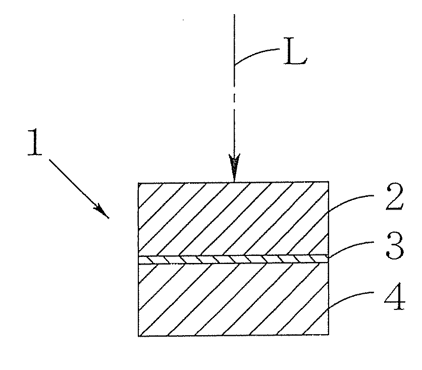
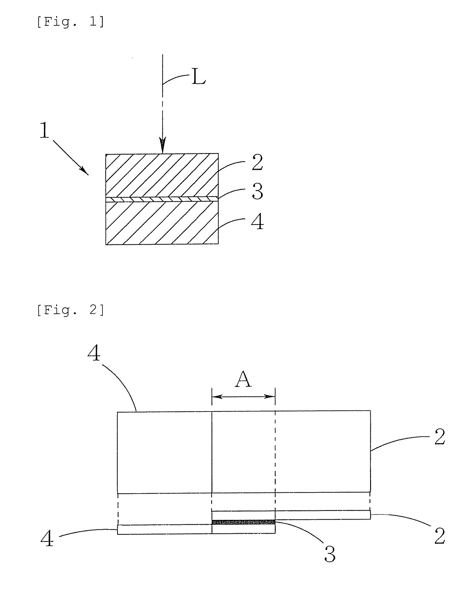
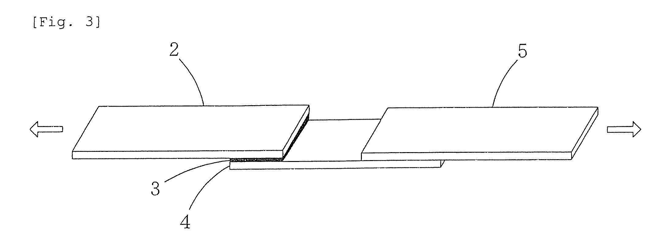
An intermediate member for laser bonding (3) to be sandwiched, in order to bond a first member (2) and a second member (4) using a laser welding method, between the first member (2) made of a material capable of transmitting laser beams and the second member (4) made of a material which is the same as or different from that of the first member (2) before irradiation with laser beams, the intermediate member for laser bonding (3) having tackiness. This intermediate member for laser bonding (3) can be used for bonding of various materials, and thus a high bonding strength can be attained.

Description

TECHNICAL FIELD[0001]The present invention relates to an intermediate member for laser bonding to be sandwiched between a first member and a second member prior to irradiation with laser beams in order to use a laser welding method to bond the first member made of a material capable of transmitting laser beams and the second member made of a material which is the same as or different from the first member. Furthermore the present invention relates to a method of bonding and a bonded article using the intermediate member.BACKGROUND ART[0002]A method of bonding members which are made of resins, or made of different materials such as a resin and a material other than the resin for example includes a method of bonding by irradiation with laser beams (so-called laser welding method). This is a method in which a transmitting member capable of transmitting laser beams is brought into contact with a nontransmitting member incapable of transmitting laser beams and then laser beams are irradi...

Claims


Application Information

Patent Timeline
IPC IPC(8): B32B27/30B32B37/06C08L31/02B29C65/16B29C65/48B29L9/00B32B25/14C09J5/00C09J7/00C09J7/35C09J7/38C09J11/00C09J153/00
CPCB23K26/203B29C65/4815B29C65/1616B29C65/1635B29C65/1661B29C65/1677B29C65/168B29C65/5057B29C65/8215B29C66/1122B29C66/43B29C66/712B29C66/73112B29C66/742B29C66/7422B29C66/74281B29C66/74283B29C66/7461B29C66/74611B29C66/7465B29K2021/00B29K2021/003B29K2023/00B29K2023/06B29K2023/12B29K2025/00B29K2027/06B29K2033/12B29K2055/02B29K2059/00B29K2063/00B29K2067/00B29K2067/006B29K2069/00B29K2075/00B29K2077/00B29K2105/0085B29K2105/24B29K2305/00B29K2305/02B29K2305/10B29K2305/12B29K2309/02B29K2309/04B29K2309/08B29K2995/0093B29C66/343B29C65/1658B23K26/421B29C66/7392B29C66/73921B29C66/7394B29C66/73941B23K26/211B23K26/60B29C66/71Y10T428/31938B29K2067/003B29K2025/06
Inventor MITOOKA, YUTAKANAGATA, KAZUYAHINO, MAKOTOURAKAMI, KAZUTOFUJITA, KAZUYA
Owner OKAYAMA PREFECTURAL GOVERNMENT
Learn More