
Image display device, image display method, and image display program

a technology of image display and image, applied in the direction of color television details, instruments, electrical devices, etc., can solve the problems of difficult to different set the viewing angle of the left and right side, normal display cannot be performed, etc., to achieve the effect of high precision, and changing the viewing angle of the display imag

Inactive Publication Date: 2010-01-14
EPSON IMAGING DEVICES CORP
View PDF9 Cites 8 Cited by
  • Summary
  • Abstract
  • Description
  • Claims
  • Application Information

AI Technical Summary

Benefits of technology

[0007]An advantage of some aspects of the invention is to provide an image display device capable of changing viewing angles of display images with high precision in image display, thus allowing a plurality of viewers to see different two-dimensional or three-dimensional images at the same time.
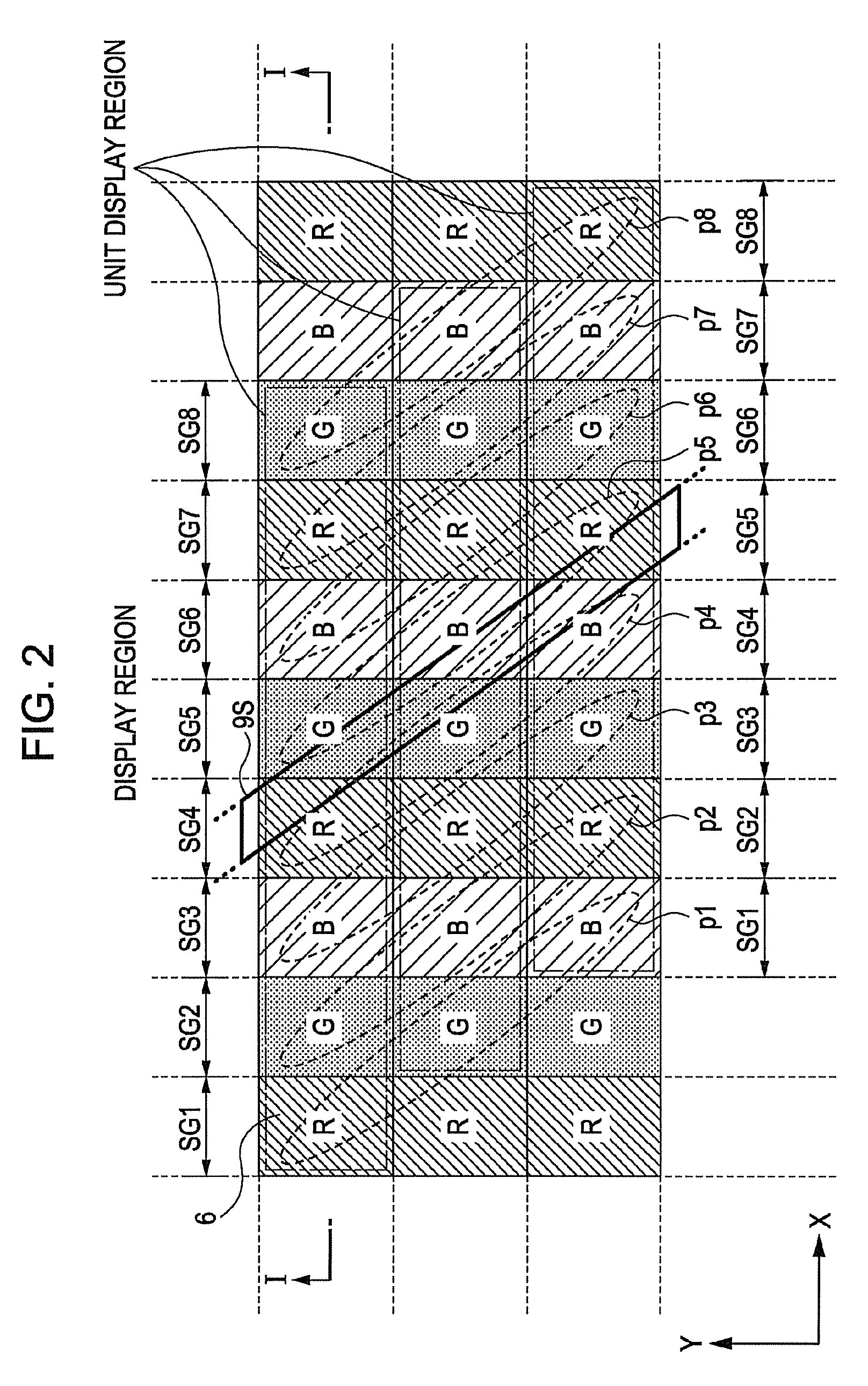
[0010]With such a structure, it is possible to change viewing angles of display images with high precision without modifying the structure of the image display device, and also the image display device can simultaneously display different two-dimensional images or three-dimensional images to the plurality of viewers, respectively. Each of the plurality of pixels is composed of a plurality of sub-pixels whose colors are different from each other, for example, sub-pixels of RGB colors.
[0014]In the image display device, it is preferable that, of the unit display regions, the unit display regions adjacent to each other in a perpendicular direction, which is a direction perpendicular to an arrangement direction of the plurality of sub-pixels, are set such that they are misaligned with each other in the arrangement direction of the sub-pixels. With such placement, it is possible to suppress deterioration feeling of resolution in the arrangement direction of the sub-pixels.
[0018]According to a still another aspect of the invention, there is provided an image display method of displaying a plurality of images to a plurality of unit display regions adjacent to each other such that the plurality of images are visible in different directions by separating light from a plurality of pixels into light beams directing in different directions when there are unit display regions, each having a plurality of sub-pixels arranged therein, and the plurality of pixels is arranged in the adjacent unit display regions, including the steps of: supplying an identical image signal to the pixels belonging to one pixel group or different image signals to the pixels belonging to different pixel groups, respectively while making the plurality of pixels belong to one or a plurality of pixel groups; and selecting the number of pixel groups or the number of pixels included in each pixel group. According to the method, it is possible to change viewing angles of display images with high precision without modifying the structure of the image display device.
[0019]According to a still another aspect of the invention, there is provided an image display program executed in a control portion which controls an image display device in which there are unit display regions, each having a plurality of sub-pixels arranged therein, a plurality of pixels is arranged in plural unit display regions adjacent to each other, and a plurality of images displayed at the plurality of unit display regions adjacent to each other is visible in different directions by separating light from the plurality of pixels into light beams directing in different directions. The image display program causes the control portion to function as: an image signal supply unit which makes the plurality of pixels belong to one pixel group or a plurality of pixel groups and supplies an identical image signal to the pixels belonging to one pixel group and different image signals to the pixels belonging to different pixel groups; and a selection unit which selects the number of pixel groups or the number of pixels included in each pixel group. According to this program, it is possible to change viewing angles of display images with high precision without modifying the structure of the image display device.

Problems solved by technology

However, the image display device has a problem in that a viewer seated behind the driver can only see the navigation image and a viewer seated in the center of the back seats may see a mixture of the image of the car navigation system and the image of the DVD or the television set.
However, such a method is disadvantageous in that there is a possibility that normal display can not be performed when the parallax barrier is displaced.
However, this method also has a problem in that it is difficult to differently set left and right side viewing angles, although it is possible to expand and narrow the viewing angles.

Method used


Image

  • Image display device, image display method, and image display program
  • Image display device, image display method, and image display program
  • Image display device, image display method, and image display program

Examples


Embodiment Construction

[0038]Embodiments of the invention will be described below with reference to the accompanying drawings.

Image Display Device

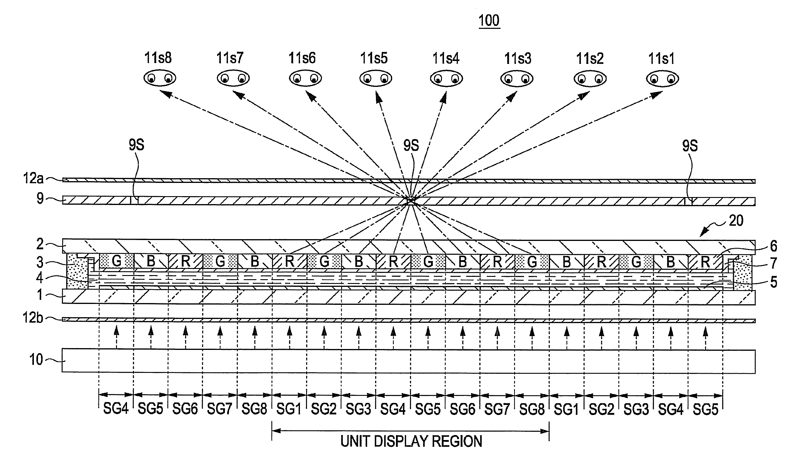
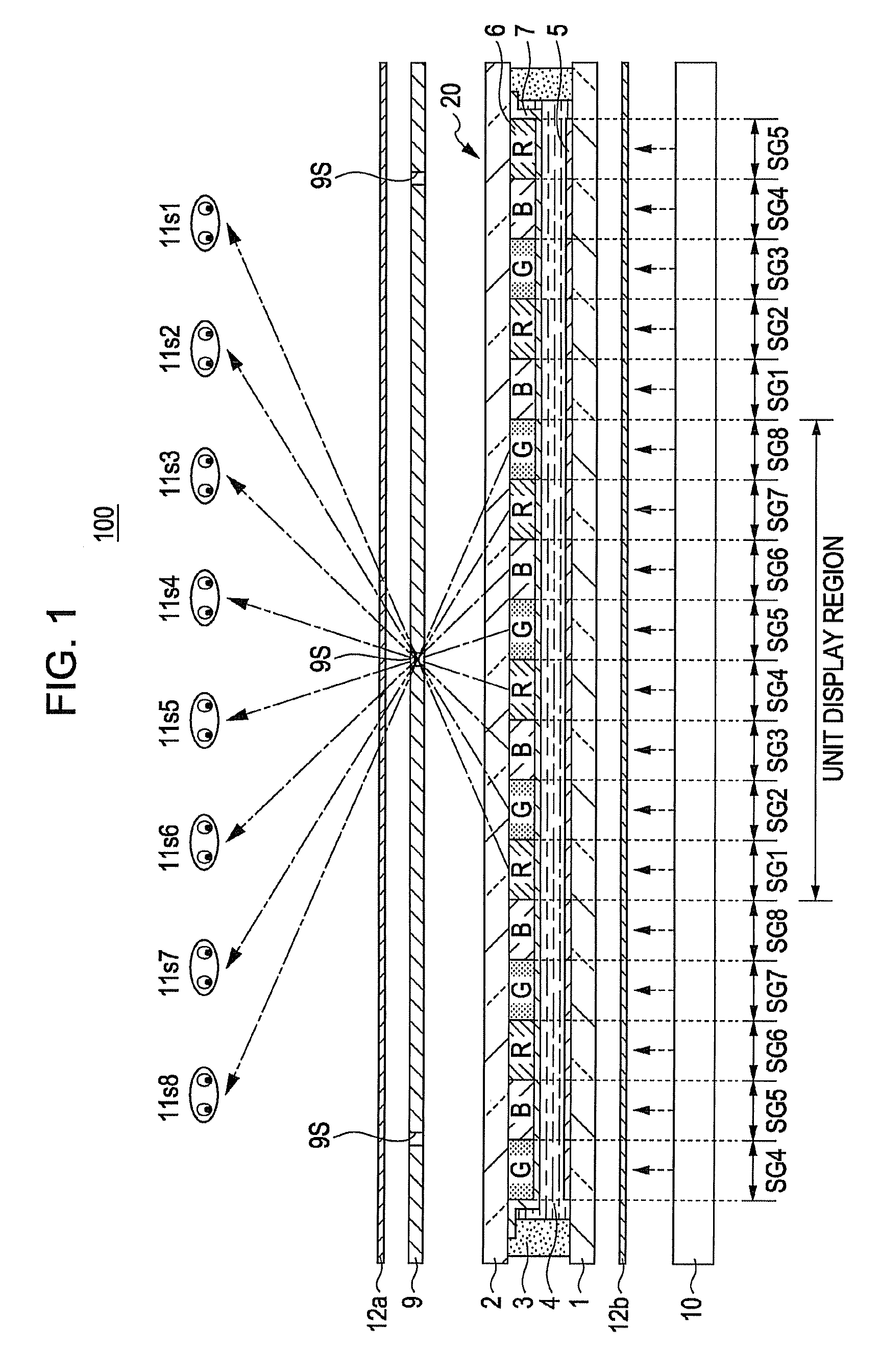
[0039]FIG. 1 is a cross-sectional view illustrating an image display device 100 according to this embodiment. The image display device 100 according to this embodiment has a parallax barrier system. Accordingly, the image display device 100 can perform a dual-image display by which different images can be viewed by to a plurality of different view points 11s1 to 11s8 in different viewing positions.

[0040]As shown in FIG. 1, the image display device 100 according to this embodiment mainly includes a parallax barrier 9, a liquid crystal panel 20, and a lighting device 10.

[0041]The liquid crystal panel 20 has a structure in which substrates 1 and 2 are attached to each other with a sealing member 3 in between. Liquid crystals 4 are sealed in a gap between the substrates 1 and 2. Pixel electrodes 5 are formed on the substrate 1 so as to correspond to every dot of sub...


PUM


Abstract

An image display device includes display regions, each having sub-pixels arranged therein, a pixel groups, each including a pixels, each pixel being composed of the sub-pixels included in the unit display regions adjacent to each other, a separating element which separates light of the image into light beams directing in different directions in the unit of one pixel group, an image signal supply unit which supplies an identical image signal or different image signals to the pixel groups, respectively, and a selection unit which selects a number of pixel groups or a number of pixels included in the pixel group.

Description

BACKGROUND[0001]1. Technical Field[0002]The present invention relates to an image display device, an image display method, and an image display program suitable for the display of various kinds of information.[0003]2. Related Art[0004]As an example of an image display device, there is a two-picture display device presenting different images to viewers positioned at different positions, respectively, or a three-dimensional image display device displaying a three-dimensional image. As such image display devices, for example, Japanese Patent No. 3503925 discloses a parallax barrier type image display device using a parallax barrier and JP-A-2005-78078 discloses a lenticular lens type image display device using a lenticular lens.[0005]These image display devices are typically mounted in car navigation systems. In such a case, the image display devices serve as two-picture display devices. That is, a navigation image is visible if the image display device is viewed from the driver's seat...

Claims


Application Information

Patent Timeline
Patent Type & Authority Applications(United States)
IPC IPC(8): H04N13/04G09G3/36
CPCG02F1/1323G02F1/133526G02F2201/52G09G3/003G09G3/3648H04N13/0497H04N13/0409H04N13/0415H04N13/0422H04N13/0447H04N13/0454H04N13/0404H04N13/305H04N13/324H04N13/31H04N13/359H04N13/317H04N13/398H04N13/351
Inventor YASUI, MASASHI
Owner EPSON IMAGING DEVICES CORP
Learn More