
Ventilated animal cage assembly

a cage and ventilation technology, applied in the field of animal cages, can solve the problems of increasing spreading disease, uneven airflow, etc., and achieve the effects of reducing the transfer of contaminants, reducing the risk of infection, and improving the overall health of animals

Inactive Publication Date: 2010-01-14
VERHAGE RICHARD +2
View PDF15 Cites 21 Cited by
  • Summary
  • Abstract
  • Description
  • Claims
  • Application Information

AI Technical Summary

Benefits of technology

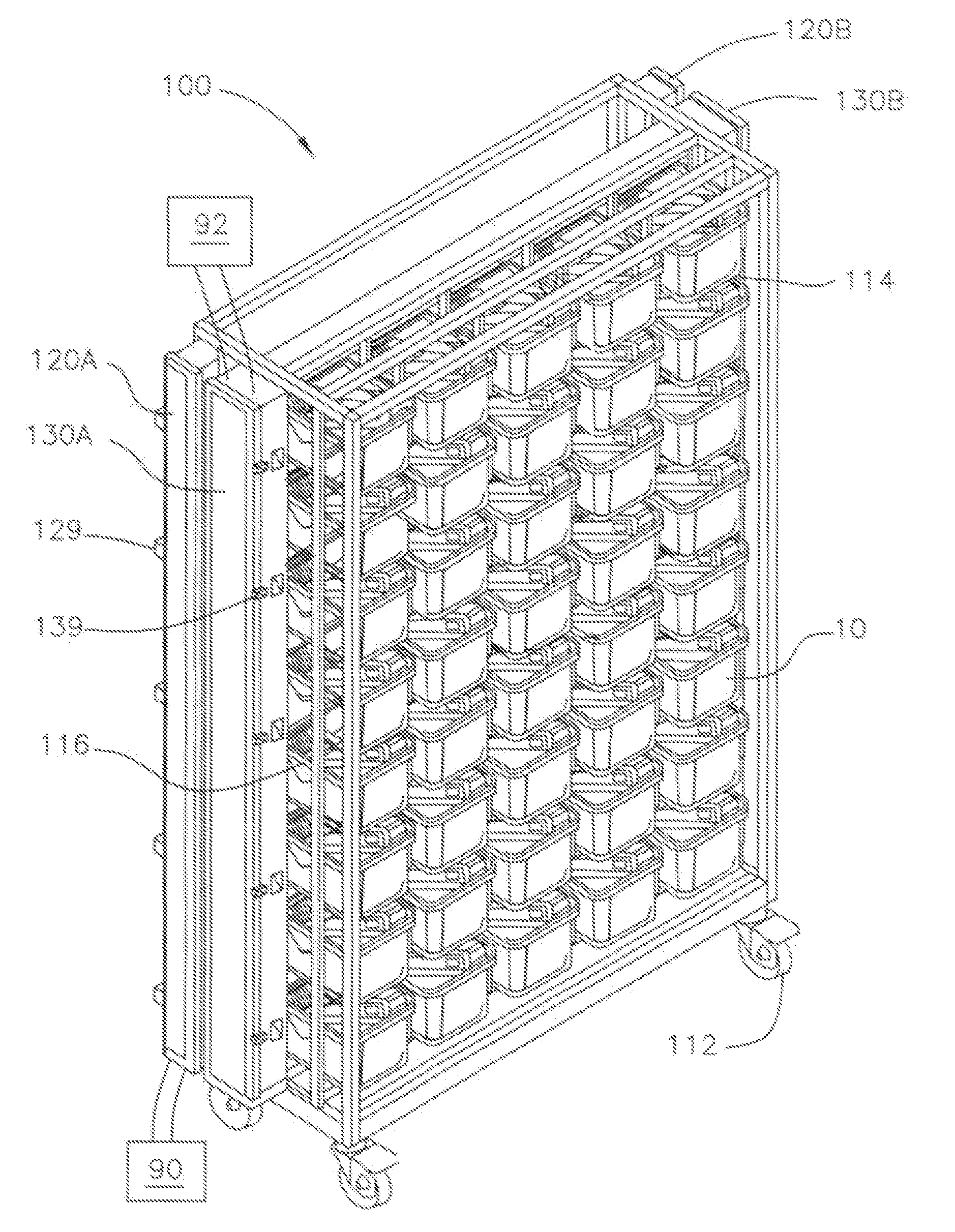
"The present invention is a ventilated rack system for animal cages that improves upon previous designs. It includes a frame with multiple cage bays for holding animal cages, and at least two vertical ducts for ventilation. The ducts are connected by a cross-frame channel that delivers ventilation air to the cages. This system helps to regulate climate control, improve animal health, and reduce the transfer of contaminants from inside the cages to the external air supply."

Problems solved by technology

Housing animals in close proximity with poor ventilation creates a number of potential issues, including increased risk of infection, spread of disease, transfer of viruses and bacteria, odors, rapid temperature fluctuation, uneven airflow, and poor overall hygiene.
These problems can affect not only animal health and well being, but also the reliability and predictability of data furnished through scientific experiments and testing done on the animals.
However, even with these improvements, due to the inherent nature of animal storage, there are many problems that arise regarding cleaning of the cages, inadequate ventilation, unwanted cross-contamination, cage durability, ease of use etc .

Method used


Image

  • Ventilated animal cage assembly
  • Ventilated animal cage assembly
  • Ventilated animal cage assembly

Examples


Embodiment Construction

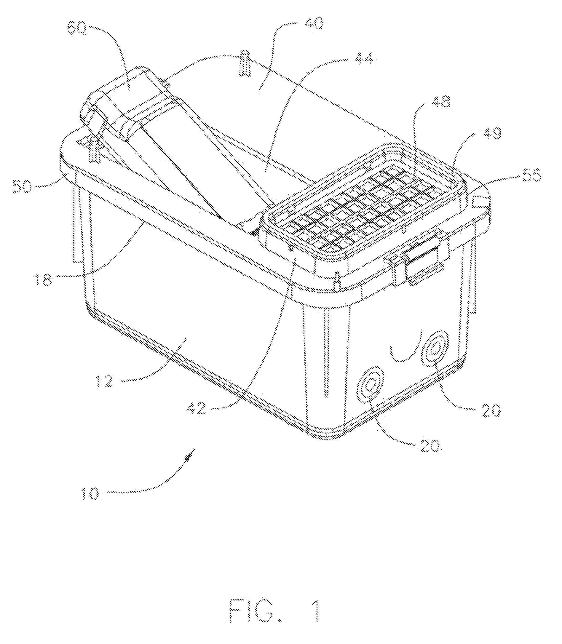
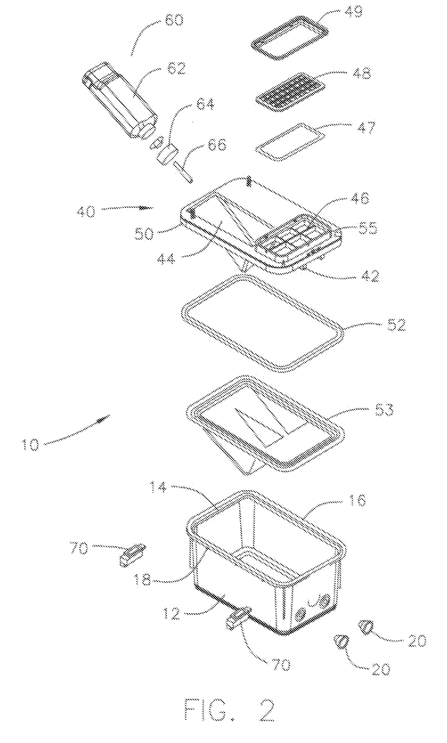
[0025]In one embodiment of the present invention, as illustrated in FIGS. 1 and 2, an animal cage 10 is shown, formed from a container base 12, a lid 40 and a water unit 60.

[0026]Beginning with container base 12, this portion is the principal housing for the animals. Typically, animal bedding is placed on the bottom and other such items including food dishes and animal toys. Base 12 is preferably constructed of a high durability polymer that can withstand prolonged use and frequent cleanings (e.g. autoclave), such as polycarbonate, polysulfone or polyetherimide, however the invention is not limited in this respect. Any polymer which is sufficiently durable for sustained use and cleaning may be used for base 12 in conjunction with the present invention.

[0027]As shown in FIG. 2, base 12 has a circumferential lip 14 that extends perpendicularly away from the top of the side walls and an upward flange 16, together configured to receive the connecting portions of lid 40.

[0028]Furthermore...


PUM


Abstract

A ventilated rack system includes a frame having a plurality of cage bays, each for supporting an animal cage. At least two first and second vertical ventilation input ducts are disposed, one on either side of the frame. At least one air input cross-frame channel connects the first vertical ventilation input duct on one side of the frame to the second vertical ventilation input duct on the opposite side of the frame, where the air input cross-frame channel is configured to dispense ventilation air into the cages in the plurality of cage bays.

Description

RELATED APPLICATION [0001]This application is related to and claims the benefit of priority from U.S. Provisional Patent Application No. 60 / 723,262, filed on Oct. 3, 2005, the entirety of which is incorporated herein by reference.FIELD OF THE INVENTION [0002]The present invention relates to animal cages. More particularly, the present invention relates to multiple ventilated animal cage racks.BACKGROUND OF THE INVENTION [0003]In the field of commercial application animal cages there are a number of existing arrangements for maintaining numerous animal cages within a single ventilated rack system. For example, larger testing projects at commercial and higher learning institutions may require upwards of hundreds of manageable habitats for maintaining the animals required. A typical arrangement may require the maintaining of several hundred lab mice, requiring a hundred or more separate cages.[0004]As such, multi-cage ventilated rack systems have been developed for easier management of...

Claims


Application Information

Patent Timeline
Patent Type & Authority Applications(United States)
IPC IPC(8): A01K1/03
CPCA01K1/031A01K1/0047
Inventor VERHAGE, RICHARDVERHAGE, HENRYVERHAGE, GLENN
Owner VERHAGE RICHARD
Learn More