
Non-magentic access floor system for use in electronic imaging rooms

a technology of electronic imaging and access flooring, which is applied in the direction of flooring, roofs, ceilings, etc., can solve the problems of not efficiently cooling equipment, affecting the operation of emi machines and their output, and requiring cooling equipment, etc., to achieve the effect of elimination of metal on metal conta

Inactive Publication Date: 2010-01-14
FRANK PENDERGAST
View PDF9 Cites 9 Cited by
  • Summary
  • Abstract
  • Description
  • Claims
  • Application Information

AI Technical Summary

Benefits of technology

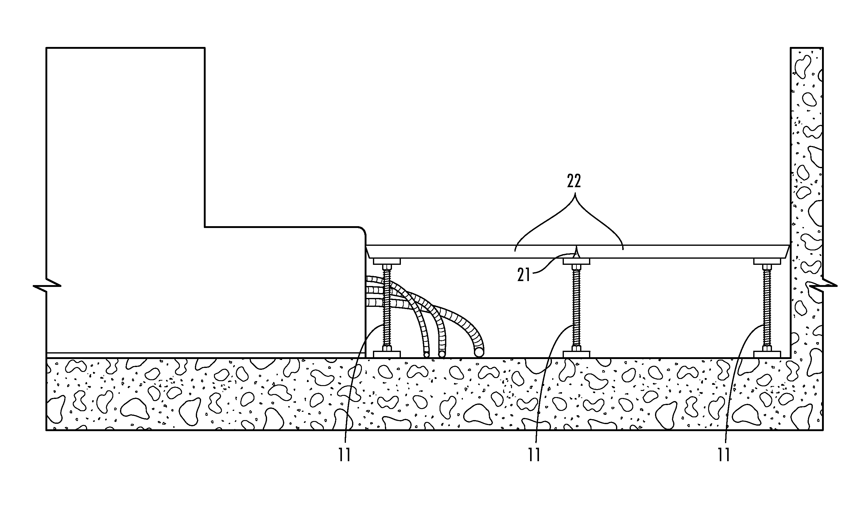
[0009]In this regard, the present invention provides an improved access system that employs floor panels and pedestals that have no metal on metal component contact and is therefore totally non-magnetic. The pedestal assembly has a stainless steel support rod that extends between a non-metallic cap and a non-metallic base support. Since the support post cap and base are not made of metal and since the support post within the pedestal does not interface or attach to another metal component, and there is no metal on metal contact within the system. Further, the floor panels sit on top of a non-metallic cap, which in turn is attached to a non-metallic pedestal head, and again resulting in the elimination of metal on metal contact.
[0010]Accordingly, the system of the present invention provides an improved access floor that does not exhibit the minute movements that cause difficulty to the operators of EMI machines in calibrating those machines for their proper and best use. Moreover, the complete elimination of metal in the access panels themselves provides the users of the current generation of more powerful EMI machines with visual output absent any interference, white pixel noise or static.
[0011]It is therefore an object of the present invention to provide an access floor construction that does not experience minute movements that would tend to degrade or interfere with the images generated by the new generation of EMI machines that are using more powerful magnets than has been the case in the past. It is a further object of the present invention to provide an access floor system that eliminates shifting of the floor panels against the underlying pedestals in order to thereby overcome the calibration problems currently being experienced by operators of existing electric magnetic imaging machines.

Problems solved by technology

In addition, the large pieces of equipment maintained in a confined space generated large quantities of heat, thus requiring cooling equipment.
Further, the air conditioning was pumped into the room typically using wall or ceiling registers in a manner that did not efficiently cool the equipment.
The access floor used in such rooms must use non-magnetic materials in the floor construction or else even minute movement in the floor caused by the strong magnetic field generated by the EMI machine will interfere with the operation of the EMI machine and its output.
However, as the magnets used in the EMI machines have become increasingly more powerful they have started inducing minute movements even in the floors that are constructed using aluminum components.
The difficulty is that as aluminum panels and pedestals of the raised floor move, they cause white pixel noise that interferes with and degrades the images generated by the newer EMI machines.
Further, the movement of the aluminum raised floor construction due to the strong magnetic field generated by the EMI machines causes difficulties calibrating the EMI machines.
This construction method however still has significant problems due to the questionable durability of the weather-strip and latex materials.

Method used


Image

  • Non-magentic access floor system for use in electronic imaging rooms
  • Non-magentic access floor system for use in electronic imaging rooms
  • Non-magentic access floor system for use in electronic imaging rooms

Examples


Embodiment Construction

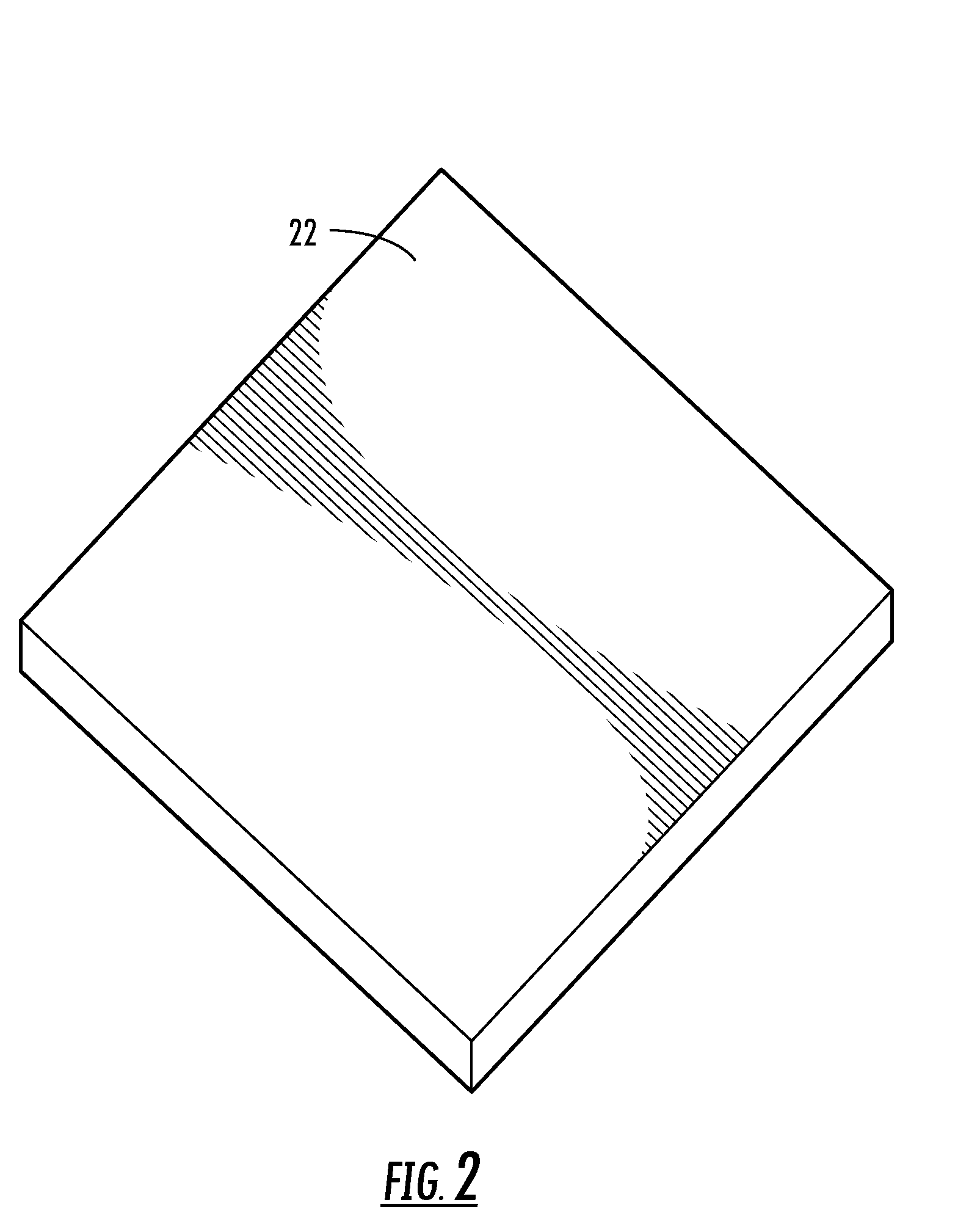
[0019]Now referring to the drawings, one embodiment of the access floor system of the present invention is shown and generally illustrated in the figures. As can be seen in the most general terms, an access floor system is provided for installation over a subfloor. The access floor system includes a pedestal assembly that is configured and arranged to be affixed to the subfloor and a floor panel formed from non-metallic materials that is supported in spaced relation above the subfloor by a plurality of said pedestal assemblies.

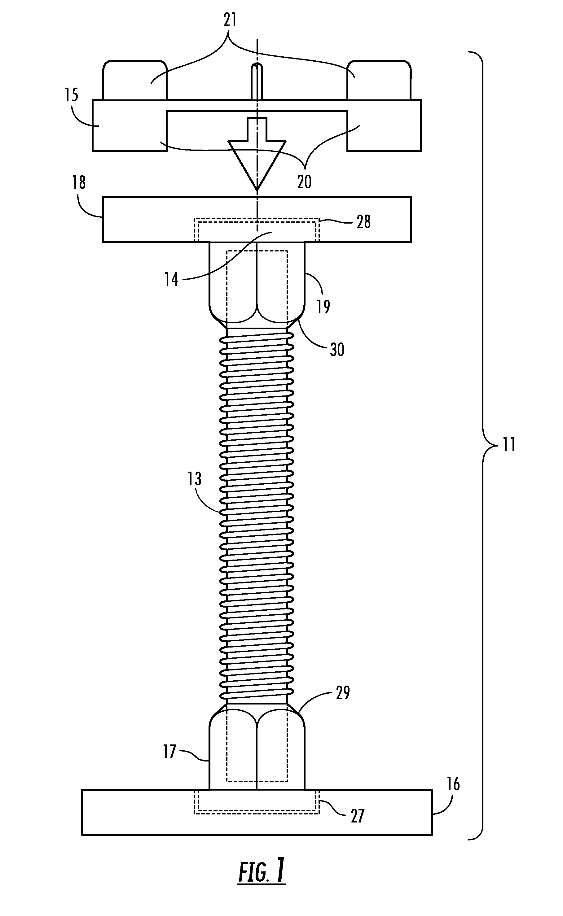
[0020]Turning now to FIG. 1, the pedestal assembly 11 is shown in detail. The pedestal assembly includes a polymer pedestal base 16 having a recess 27 in a top surface thereof a polymer pedestal head 18 having a recess 28 in a bottom surface thereof and a rod support 13 having a first end 29 configured to be received and retained in said recess 27 in the pedestal base 16 and a second end 30 configured to be received and retained in the recess 28 in said pedest...


PUM

PropertyMeasurementUnit
Magnetic fieldaaaaaaaaaa
Metallic bondaaaaaaaaaa
Perimeteraaaaaaaaaa

Abstract

An access system is provided that employs a floor panel and pedestal assembly designed to provide a non-magnetic environment with no metal on metal contact making the system particularly suited for EMI machine room use. The access floor eliminates the difficulty in calibrating the EMI machine due to minute movement in the access floor panels that arises from metal on metal contact. Moreover, the system ensures that the floor panels themselves contain no metallic parts thereby eliminating the static white pixel noise associated with the more powerful magnets now used in the current generation of EMI machines. Thus a considerably more versatile access floor is provided that can support the need of the current generation of EMI machines to be movement free and to not generate static interference in their visual output.

Description

CROSS-REFERENCE TO RELATED APPLICATIONS[0001]This application is related to and claims priority from earlier filed U.S. Provisional Patent Application No. 61 / 134,732, filed Jul. 14, 2009.BACKGROUND OF THE INVENTION[0002]The present invention relates generally to access flooring systems. More specifically, the present invention relates to an improved access flooring system that is constructed entirely from non-magnetic materials in a manner that allows use of the system in applications where a strong magnetic field exists.[0003]During the early development of computers and related technology, the equipment was commonly housed in centralized computer rooms. This equipment generally consisted of several pieces of bulky equipment that needed power cabling and communication cabling between each piece. In addition, the large pieces of equipment maintained in a confined space generated large quantities of heat, thus requiring cooling equipment. All of the cabling that ran between the equip...

Claims


Application Information

Patent Timeline
IPC IPC(8): E04F15/024E04C2/20
CPCE04F15/02405E04F15/0247E04F15/02452E04F15/02423
Inventor PENDERGAST, JOHN B.
Owner FRANK PENDERGAST
Learn More