
Method of manufacturing a membrane-electrolyte assembly for fuel cells, and membrane-electrolyte assembly

Inactive Publication Date: 2009-12-31
TOYOTA JIDOSHA KK
View PDF3 Cites 3 Cited by
  • Summary
  • Abstract
  • Description
  • Claims
  • Application Information

AI Technical Summary

Benefits of technology

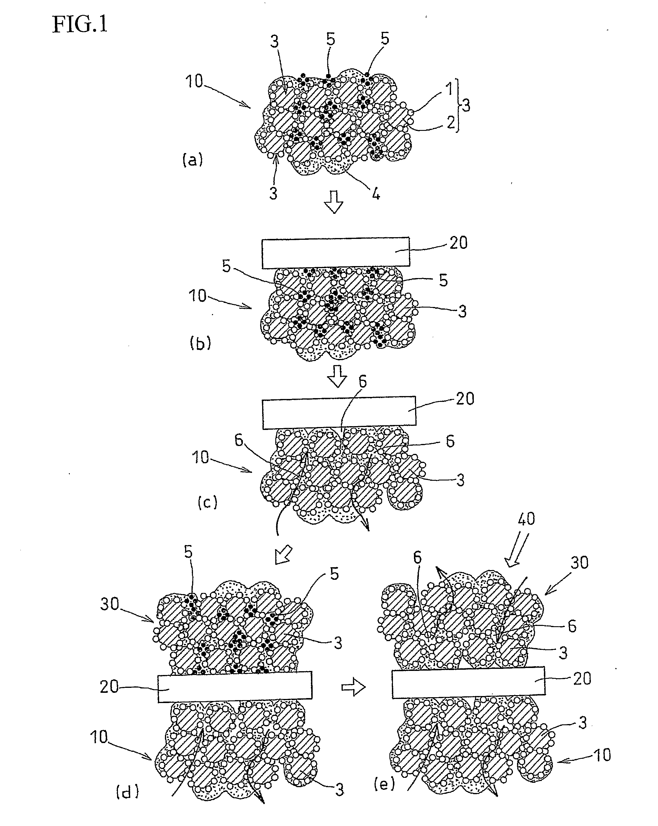
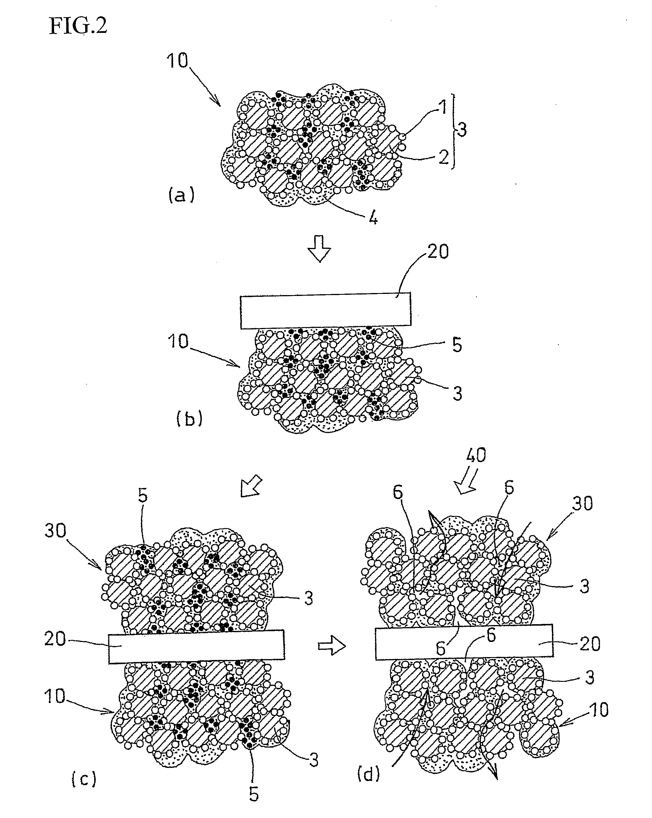
[0021]In accordance with the present invention, in a method of manufacturing a membrane-electrolyte assembly using the solution three-layer coating method, the seeping of the electrolyte solution into the pores in the catalyst layer can be prevented. Thus, a membrane-electrolyte assembly with high generation efficiency having a uniform gas diffusibility and drainage property can be easily obtained. It also becomes possible to easily manufacture a membrane-electrolyte assembly having a catalyst layer with a desired pore capacity.

Problems solved by technology

When manufacturing the membrane-electrolyte assembly by the direct coating method or the transfer method, there is the problem of insufficient bond between the electrolyte layer and the catalyst layer, which causes an interface debonding during electricity generation and results in a decrease in generation efficiency.
In the case of the transfer method, there is the problem of possible damage to the electrolyte layer by the pressure during transfer.
This requires multiple manufacturing steps and results in a decrease in productivity.

Method used


Image

  • Method of manufacturing a membrane-electrolyte assembly for fuel cells, and membrane-electrolyte assembly
  • Method of manufacturing a membrane-electrolyte assembly for fuel cells, and membrane-electrolyte assembly
  • Method of manufacturing a membrane-electrolyte assembly for fuel cells, and membrane-electrolyte assembly

Examples


example 1

[0044]An air-electrode catalyst layer ink (first catalyst layer ink), a fuel-electrode catalyst layer ink (second catalyst layer ink), and an electrolyte layer ink were used. The air-electrode catalyst layer ink (first catalyst layer ink) and the fuel-electrode catalyst, layer ink (second catalyst layer ink) were prepared in four kinds each, having different amounts of the pore-forming agent added therein. Specifically, an ultra fine particle of ammonium carbonate having a particle diameter of 10 nm was added as the pore-forming agent in amounts of 40 wt %, 30 wt %, 20 wt %, and 10 wt % with respect to the weight of the solid components of the catalyst layer ink (carbon, platinum, and electrolyte). Ammonium carbonate starts to sublimate at temperature of 60° C. or higher, and completely sublimates at 130° C.

[0045]Each of the first catalyst layer inks was applied to the substrate sheet and subjected to drying treatment at temperature of 60° C. or lower. After drying treatment, the el...

example 2

[0047]Membrane-electrolyte assemblies were fabricated in the same way as Example 1 with the exception that the pore-forming agent consisted of an ultra fine particle of lithium carbonate having a particle diameter of 10 nm was used, instead of ammonium carbonate. FIG. 7 shows the relationship between their pore capacities and their ratios of lithium carbonate added. Also, with the four types of membrane-electrolyte assemblies, fuel cell modules were prepared, and their generation efficiency was tested in terms of the relationship between voltage and current density. The result is shown in FIG. 8.

example 3

[0050]A membrane-electrolyte assembly was fabricated in the same way as Example 1 with the exception that the air-electrode catalyst layer ink (first catalyst layer ink) and the fuel-electrode catalyst layer ink (second catalyst layer ink) were prepared each in three types, having different amounts of pore-forming agent added, namely: 0 wt %; 20 wt %; and 40 wt %. The catalyst layer ink with the ratio of pore-forming agent added 0 wt % was used in an outer-most layer. The catalyst layer ink with the ratio of pore-forming agent added 20 wt % was used in an intermediate layer. The catalyst layer ink with the amount of pore-forming agent added 40 wt % was used in a layer adjacent to the electrolyte layer.

[0051]With the thus fabricated membrane-electrolyte assembly, a fuel cell module was prepared, and its generation efficiency was tested in terms of the relationship between voltage and current density in the same way as in Example 1. The result is shown in FIG. 9 with reference to “Wit...


PUM


Abstract

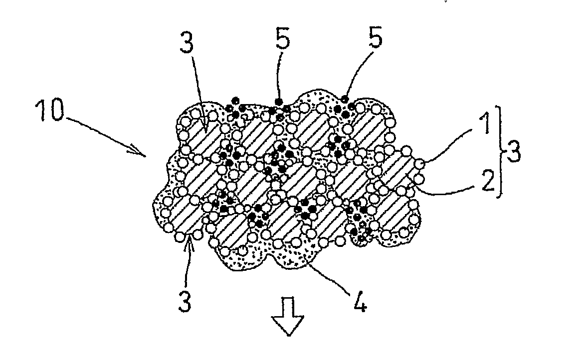
A method of manufacturing a membrane-electrolyte assembly by a solution three-layer coating method enables the manufacture of a membrane-electrolyte assembly having a high generation efficiency in which the seeping of the electrolyte solution into the pores in the catalyst layer is prevented. The method comprises performing the application of individual inks and drying treatment for a first catalyst layer 10, an electrolyte layer 20, and a second catalyst layer 30 in order to manufacture a membrane-electrolyte assembly 40. A pore-forming agent 5 is added in the ink for the first catalyst layer 10, the agent consisting of a substance that remains at temperature at which the first catalyst layer 10 is subjected to drying treatment and that dissolves or sublimates and disappears at temperature at which the electrolyte membrane 20 is subjected to drying treatment. The ink for the electrolyte layer 20 is applied to the first catalyst layer 10. Pores in the first catalyst layer 10 are blocked with the pore-forming agent 5 so that the electrolyte does not seep into the first catalyst layer 10. The electrolyte layer 20 is subjected to drying treatment at temperature higher than the temperature of drying treatment of the first catalyst layer 10. As a result, the pore-forming agent 6 in the first catalyst layer 10 dissolves or sublimates and disappears, thereby forming pores 6.

Description

TECHNICAL FIELD[0001]The present invention relates to a method of manufacturing a membrane-electrolyte assembly used in fuel cells, particularly polymer electrolyte fuel cells, a membrane-electrolyte assembly, and a fuel cell using the membrane-electrolyte assembly.BACKGROUND ART[0002]As an example of fuel cells, the polymer electrolyte fuel cell is known, which includes a membrane-electrolyte assembly (MA) as a major constituent element. The membrane-electrolyte assembly consists of an electrolyte membrane on one side of which an air-electrode catalyst layer is stacked and on the other side a fuel-electrode catalyst layer is stacked. The assembly is sandwiched by separators having gas channels to form an individual fuel battery called a “single cell.”[0003]Normally, the electrolyte membrane employs a Nafion (registered trademark) membrane. The air-electrode catalyst layer and the fuel-electrode catalyst layer are normally formed by either direct coating method or transfer method. T...

Claims


Application Information

Patent Timeline
IPC IPC(8): H01M8/10H01M4/88
CPCH01M4/861H01M4/8807H01M4/881Y02E60/521H01M4/8882H01M8/1004H01M2008/1095H01M4/8828Y02P70/50Y02E60/50
Inventor HAMA, YUICHIROKURUNGOT, SREEKUMAR
Owner TOYOTA JIDOSHA KK
Learn More