
Method of forming photovoltaic device lens and method of fabricating photovoltaic panel

a technology of photovoltaic devices and lens lenses, which is applied in the field of forming photovoltaic device lenses and method of fabricating photovoltaic panels, can solve the problems of difficult to make spherical convex lenses suitable for the respective photovoltaic devices, small size of spherical or granular photovoltaic devices formed by free fall or plasma-assisted cvd methods, etc., to prevent the optical characteristic of the lens from being d

Inactive Publication Date: 2005-06-09
FUJI MASCH MFG CO LTD
View PDF3 Cites 4 Cited by
  • Summary
  • Abstract
  • Description
  • Claims
  • Application Information

AI Technical Summary

Benefits of technology

[0010] Therefore, an object of the present invention is to forming suitable spherical convex lens on the surfaces of spherical or granular photovoltaic devices in an easy and cost-effective method even when the photovoltaic devices have variations in the size (diameter) and shape (sphericity) and further, manufacturing, in an easy and cost-effective method, a photovoltaic panel provided with lens and having a high generating efficiency.
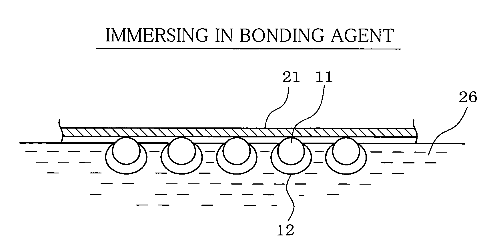
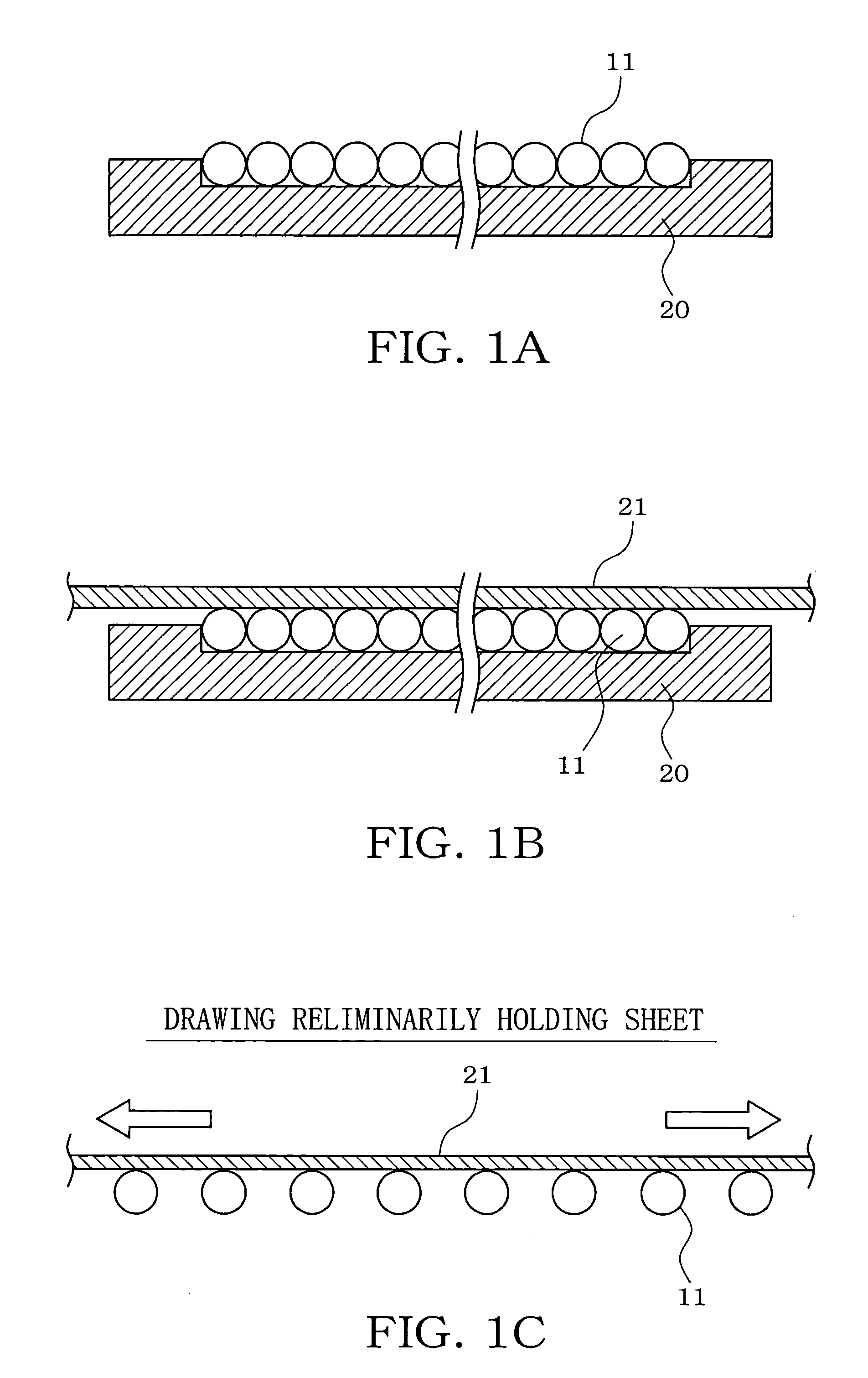
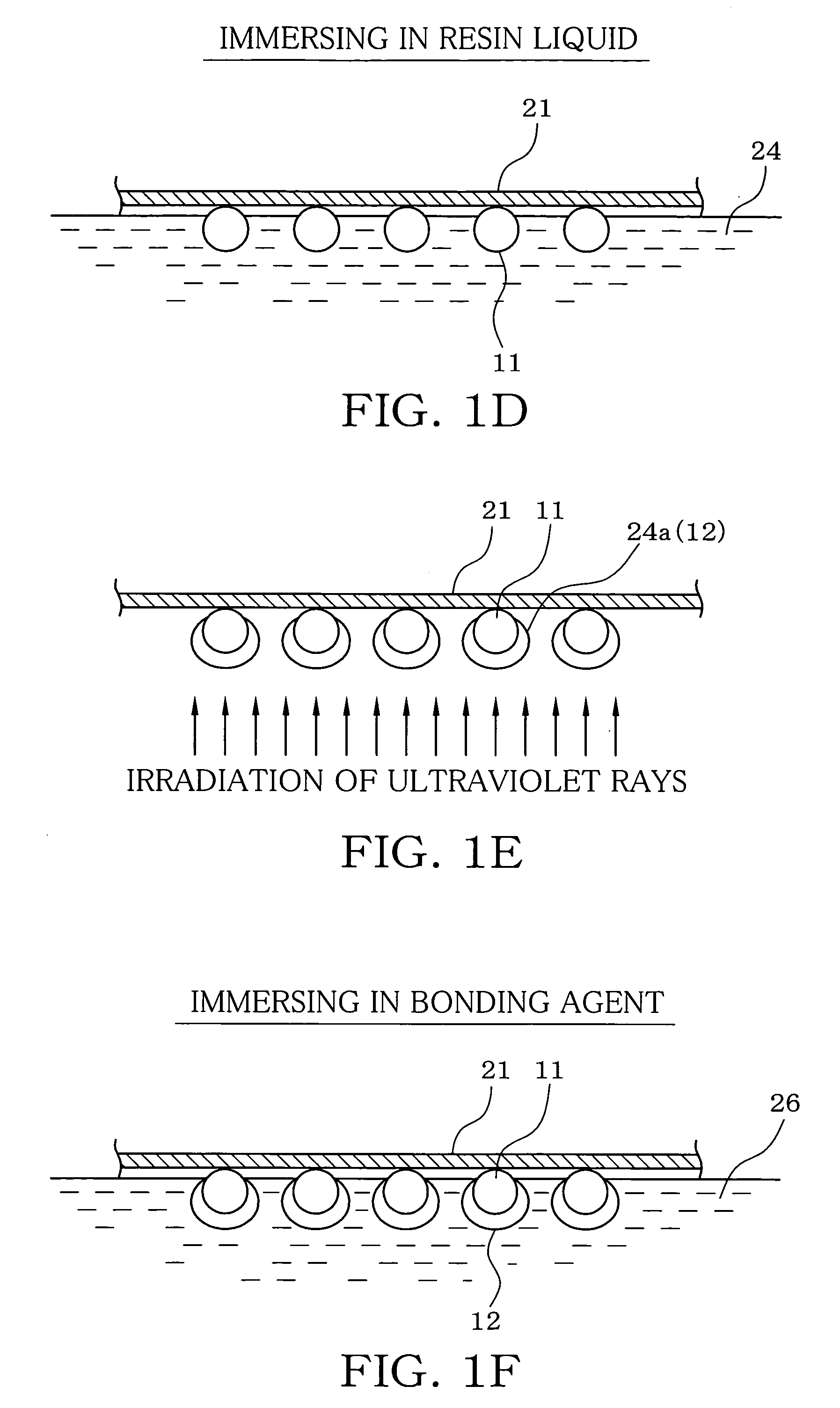
[0011] To achieve the object, the present invention is a method in which are carried out immersing the photovoltaic device in a liquid resin and lifting the photovoltaic device, thereby applying the liquid resin to the surface of the photovoltaic device, and hardening the liquid resin adherent to the surface of the photovoltaic device, thereby forming a resin lens on the surface of the photovoltaic device. Since a spherical convex lens is formed on the surface of the photovoltaic device by surface tension of the resin liquid, a suitable spherical convex lens can be formed on the surface of the photovoltaic device and the photovoltaic device can be positioned at the center of the lens even when the photovoltaic devices have variations in the size (diameter) and shape(sphericity). Moreover, no expensive forming machine, such as forming dies for injection molding, forming the lens is required, and the spherical convex lens can be formed on the surface of the photovoltaic device in an easy and cost-effective manner in which the photovoltaic device is immersed in the resin liquid, lifted and the resin liquid is hardened. Thus, optimization of the shape of lens and low costs can be achieved simultaneously.

Problems solved by technology

However, the spherical or granular photovoltaic devices formed by the free fall method or plasma-assisted CVD method are small in size and moreover have variations in the size (diameter) or shape (sphericity).
As a result, it is difficult to make spherical convex lens suitable for the respective photovoltaic devices.

Method used


Image

  • Method of forming photovoltaic device lens and method of fabricating photovoltaic panel
  • Method of forming photovoltaic device lens and method of fabricating photovoltaic panel
  • Method of forming photovoltaic device lens and method of fabricating photovoltaic panel

Examples


Embodiment Construction

[0047] One embodiment of the invention will be described with reference to the drawings. First, the structure of the photovoltaic panel 27 manufactured by the method in accordance with the embodiment of the invention with reference to FIG. 1Q.

[0048] The photovoltaic panel 27 comprises a number of spherical or granular photovoltaic devices 11 arranged side by side and integrated. Each photovoltaic device 11 includes a thin n-type semiconductor layer in the outer periphery thereof and a p-type semiconductor layer in the inner peripheral side. A method of manufacturing the photovoltaic device 11 should not be limited to a particular one and the free fall method described in international publication No. WO99 / 10935, the plasma-assisted CVD method described in JP-A-2002-60943 or another method may be employed. At a light-receiving side of each photovoltaic device 11, a spherical convex lens 12 is made from a light-transmissible ultraviolet curing resin. Each photovoltaic device 11 is bo...


PUM

PropertyMeasurementUnit
thicknessaaaaaaaaaa
elasticaaaaaaaaaa
viscosityaaaaaaaaaa

Abstract

An object of the present invention is to form suitable spherical convex lens on the surfaces of spherical or granular photovoltaic devices in an easy and cost-effective method even when the photovoltaic devices have variations in the size and shape. To achieve the object, the invention is a method in which are carried out immersing the photovoltaic device in a liquid resin and lifting the photovoltaic device, thereby causing the liquid resin to adhere to the surface of the photovoltaic device, and hardening the liquid resin adherent to the surface of the photovoltaic device, thereby forming a resin lens on the surface of the photovoltaic device. Since a spherical convex lens is formed on the surface of the photovoltaic device by surface tension of the resin liquid, a suitable spherical convex lens can be formed on the surface of the photovoltaic device and the photovoltaic device can be positioned at the center of the lens even when the photovoltaic devices have variations in the size and shape.

Description

BACKGROUND OF THE INVENTION [0001] 1. Field of the Invention [0002] This invention relates to a method of forming a lens on a surface of a spherical or granular photovoltaic device and a method of fabricating a photovoltaic panel having a number of spherical or granular photovoltaic devices arranged in an array. [0003] 2. Description of the Related Art [0004] JP-A-2001-168369 and JP-A-2002-280592 disclose spherical or granular photovoltaic devices in order to improve a generating efficiency of a photovoltaic panel which converts solar energy into electric energy, for example. The spherical or granular photovoltaic device provides a substantially constant project area (an amount of received light) when viewed from every direction of incidence of sunlight. Accordingly, even when the sun altitude is low, power generation can advantageously be performed as efficiently as when the sun altitude is high. [0005] JP-A-2001-168369 describes the photovoltaic panel including a light-transmissib...

Claims


Application Information

Patent Timeline
Patent Type & Authority Applications(United States)
IPC IPC(8): B29D11/00G02B3/00H01L31/04H01L31/0232
CPCB29D11/00365H01L31/0232G02B3/0012Y02E10/52H01L31/035281H01L31/0543
Inventor ASAI, KOICHISAKAI, KAZUTOSHISUZUKI, KAZUYAYOSHIKANE, SHUNJIICHIKAWA, HIRONOBU
Owner FUJI MASCH MFG CO LTD
Learn More