
Fiber Strand and Implantable Supporting Body Having a Fiber Strand

a technology of fiber strands and supporting bodies, which is applied in the direction of yarns, packaging goods, special packaging, etc., can solve the problems of limited mechanical possibilities of today's implantable supporting bodies, so-called stents, and no structures representing the physiological needs of surrounding tissue have been implemented according to the previous methods, and achieve positive medical effects

Inactive Publication Date: 2009-12-31
BIOTRONIK AG
View PDF2 Cites 4 Cited by
  • Summary
  • Abstract
  • Description
  • Claims
  • Application Information

AI Technical Summary

Benefits of technology

[0009]It is advantageously possible to create a controllable and individually adjustable supporting structure.
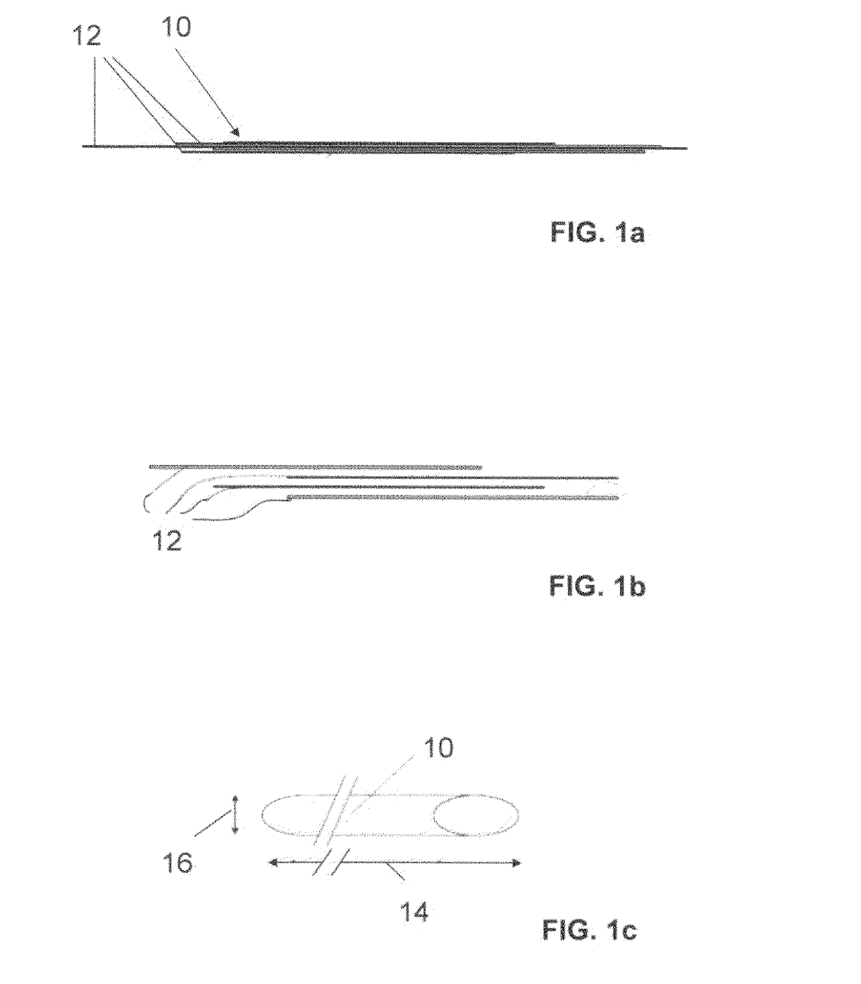
[0010]The ratio of the longitudinal extent of the individual fiber to the fiber strand longitudinal extent may preferably be in the range between 2:1 and 200,000:1, especially between 10:1 and 100,000:1. The ratio of the transverse extent of the individual fiber to the transverse extent of the fiber strand may preferably be in the range between 2:1 and 200,000:1, preferably between 10:1 and 100,000:1. The ratio of the longitudinal extent may be unrelated to the ratio of the transverse extent. Due to the preferably very short lengths and / or diameters of the individual fibers in comparison with the dimensions of a preferred supporting body formed from the fiber strand, the desired mechanical properties can be adjusted especially easily. In addition, a wide variety of materials can be combined. A large surface area can be created to accommodate drugs in the fiber strand. To have positive medical effects locally and / or regionally, a biologically active substance and / or material may also be introduced in fiber form to induce local and / or regional medically positive effects.
[0014]Likewise, an embodiment comprising a mixture of individual fibers selected from at least two of the aforementioned groups may also be possible. A wide variety of materials may thus be combined easily in the form of individual fibers. The fiber strand formed in this way can be optimized accordingly through a suitable combination of individual fibers having desired properties.
[0015]Parts of this blend and / or combination of individual fibers may already consist of medically active materials and / or medically active substances may be incorporated into individual fibers and / or remodeling products or degradation products may achieve positive medical effects.

Problems solved by technology

Today's implantable supporting bodies, so-called stents, are limited with regard to their mechanical possibilities.
For example, no structures representing the physiological needs of the surrounding tissue have been implementable according to the previous methods.
Radial or longitudinal forces or forces occurring differently in sections of the implant could in the past be imitated and simulated only individually by an implant but not as a totality, which is why the function and compatibility of such implants are limited.
Through the use of stents, the optimum vascular cross section required for primary therapeutic success can be achieved, but the permanent presence of such a foreign body initiates a cascade of microbiological processes, which may lead to a gradual occlusion of the stent.

Method used


Image

  • Fiber Strand and Implantable Supporting Body Having a Fiber Strand
  • Fiber Strand and Implantable Supporting Body Having a Fiber Strand
  • Fiber Strand and Implantable Supporting Body Having a Fiber Strand

Examples


Embodiment Construction

[0044]The invention is explained in greater detail below as an example on the basis of exemplary embodiments illustrated in the drawings in schematic diagrams.

[0045]Elements that are functionally the same or have the same effect are each labeled with the same reference numerals in the figures. The figures show schematic diagrams of the invention and form nonspecific parameters of the invention. In addition, the figures show only typical embodiments of the invention and should not restrict the invention to the embodiments depicted here.

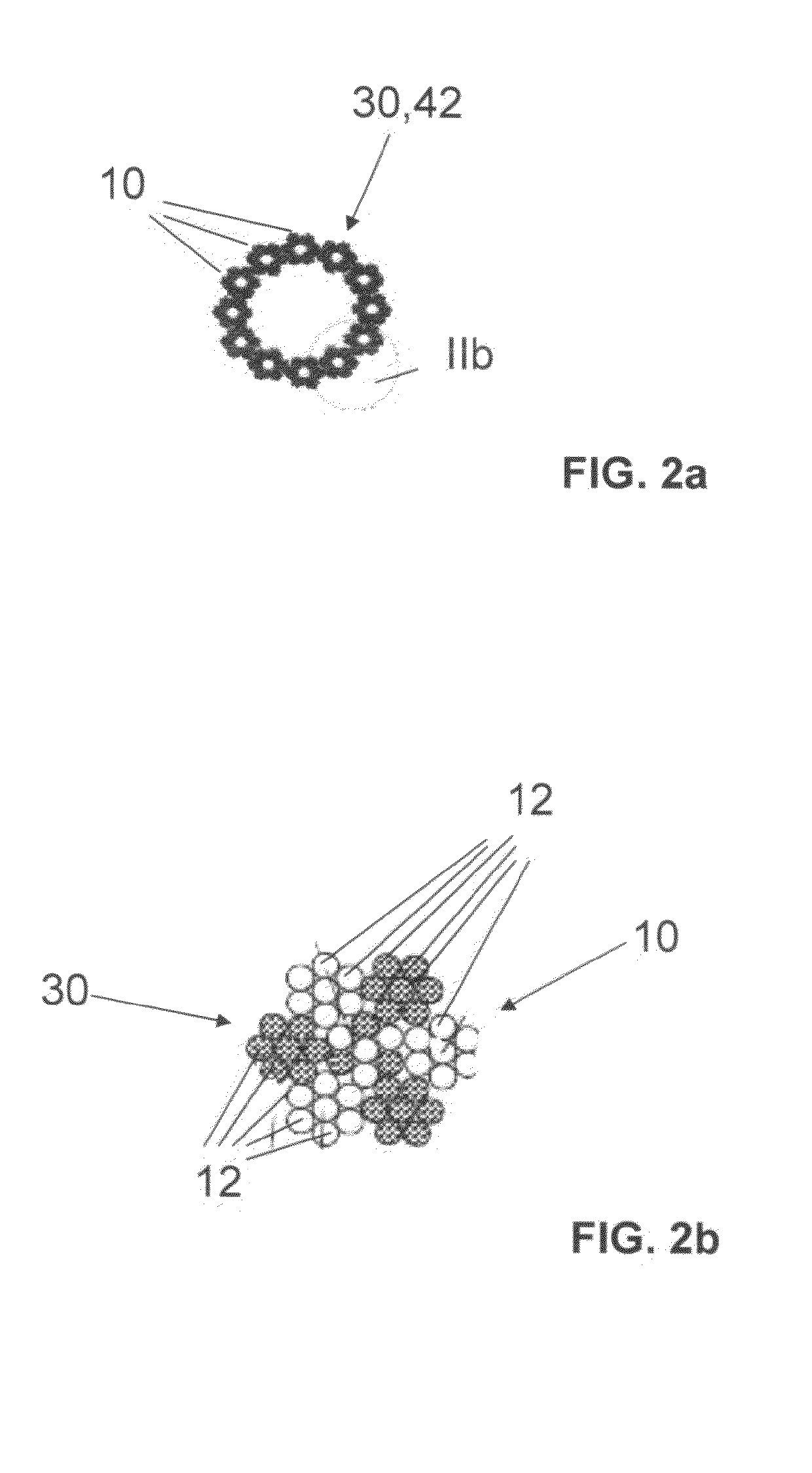
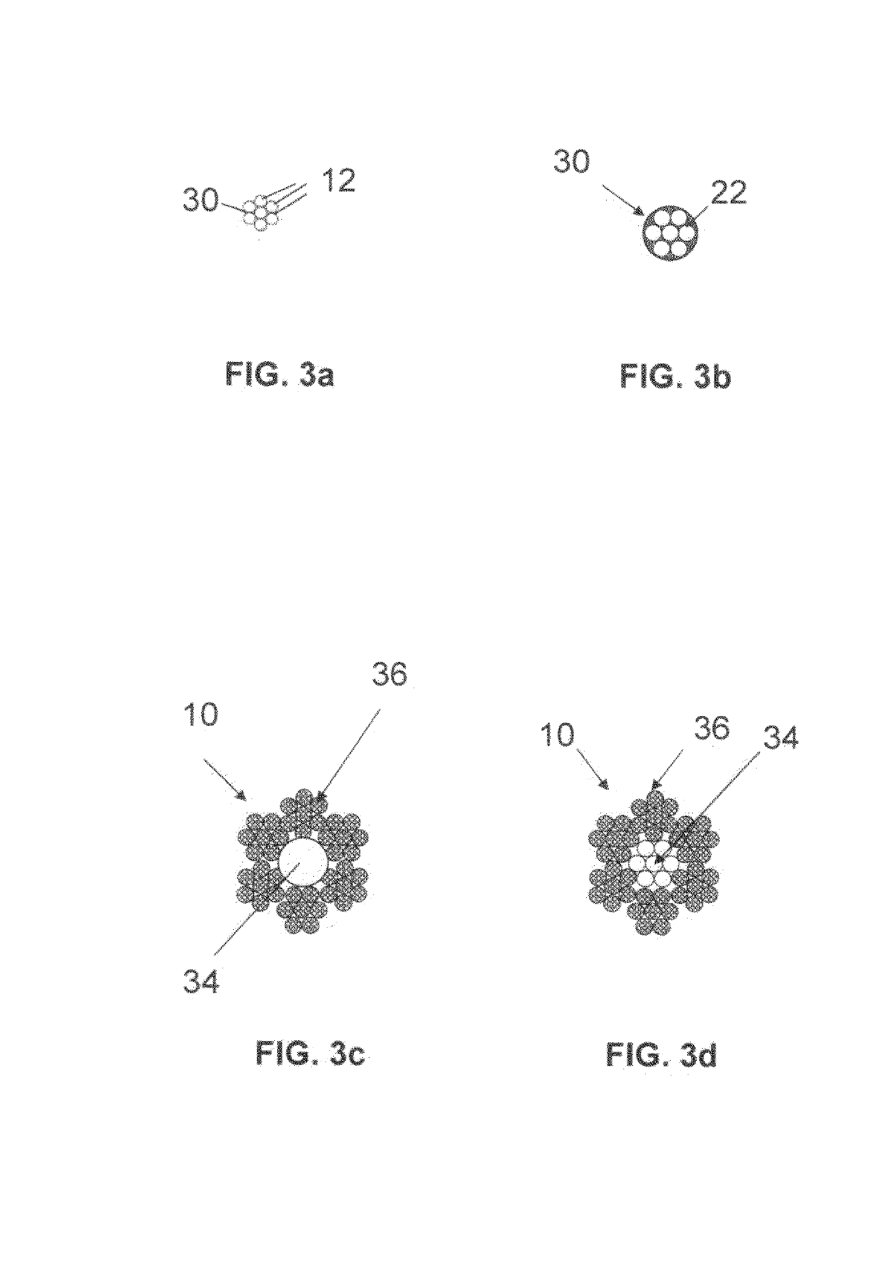
[0046]To illustrate the invention, FIG. 1a shows a preferred fiber strand 10 which may form the starting material for a preferred implantable supporting body 100 (FIG. 5) for example. The fiber strand 10 in this example is formed by a plurality of individual fibers 12, as emphasized in FIG. 1b.

[0047]The individual fibers 12 are each much shorter in length than the fiber structure longitudinal extent 14 and are much thinner in their diameter than the f...


PUM

PropertyMeasurementUnit
Biodegradabilityaaaaaaaaaa

Abstract

The invention relates to a fiber strand (10) for an implantable supporting body (100) comprising at least two individual fibers (12). The at least two individual fibers (12) are each shorter in their longitudinal extent than the longitudinal extent (14) of the fiber strand, and in their transverse extent they are each thinner than the transverse extent (16) of the fiber strand.

Description

CROSS REFERENCE TO RELATED APPLICATIONS[0001]This application claims benefit of priority to German patent application number DE 10 2008 002 641.7, filed on Jun. 25, 2008; the contents of which are herein incorporated herein by reference in their entirety.TECHNICAL FIELD[0002]The invention relates to a fiber strand and an implantable supporting body having a fiber strand including at least two fibers that are each shorter in their longitudinal extent than the longitudinal extent of the fiber strand.BACKGROUND OF THE INVENTION[0003]Today's implantable supporting bodies, so-called stents, are limited with regard to their mechanical possibilities. For example, no structures representing the physiological needs of the surrounding tissue have been implementable according to the previous methods. Radial or longitudinal forces or forces occurring differently in sections of the implant could in the past be imitated and simulated only individually by an implant but not as a totality, which is...

Claims


Application Information

Patent Timeline
IPC IPC(8): D02G1/18A61K9/10B05D3/12A61F2/82
CPCA61F2/82Y10T428/2913A61F2250/0067A61F2210/0004
Inventor BERTSCH, TORBENMULLER, HEINZ
Owner BIOTRONIK AG
Learn More