
Optical pickup, optical information reproducing apparatus and optical information reproducing method

Inactive Publication Date: 2009-12-24
SONY CORP
View PDF5 Cites 7 Cited by
  • Summary
  • Abstract
  • Description
  • Claims
  • Application Information

AI Technical Summary

Benefits of technology

[0017]According to the embodiments of the present invention, it is possible to realize an optical pickup in which the quantity of light largely fluctuates depending upon the presence or absence of a recording mark, and transmitted light with a large degree of modulation is received, whereby a reproduced signal can be produced on the basis of the subject transmitted light, and the recording mark can be detected in a high precision, an optical information reproducing apparatus and an optical information reproducing method.

Problems solved by technology

In that case, there was involved a problem that return light having the quantity of light of a prescribed amount or more cannot be obtained from the recording mark, thereby causing a lowering of the quality of reproduced signals.

Method used


Image

  • Optical pickup, optical information reproducing apparatus and optical information reproducing method
  • Optical pickup, optical information reproducing apparatus and optical information reproducing method
  • Optical pickup, optical information reproducing apparatus and optical information reproducing method

Examples


first embodiment

(1) First Embodiment

(1-1) Configuration of Optical Disc

[0033]First of all, an optical information recording medium 100 which is used as an optical information recording medium in an embodiment according to the present invention is described. Similar to the conventional CD, DVD and BD, the optical information recording medium 100 is configured in a disc shape having a diameter of about 120 mm as a whole and is provided with an opening 100H in a central portion thereof.

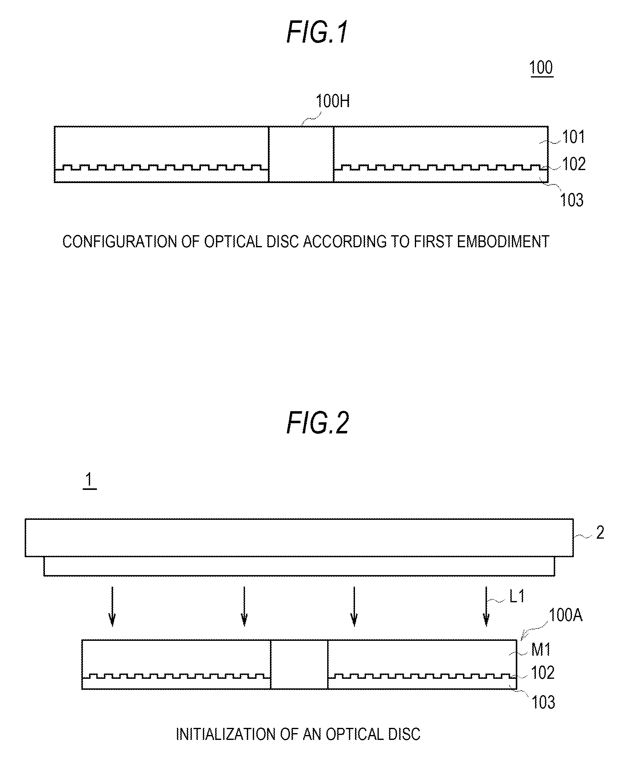
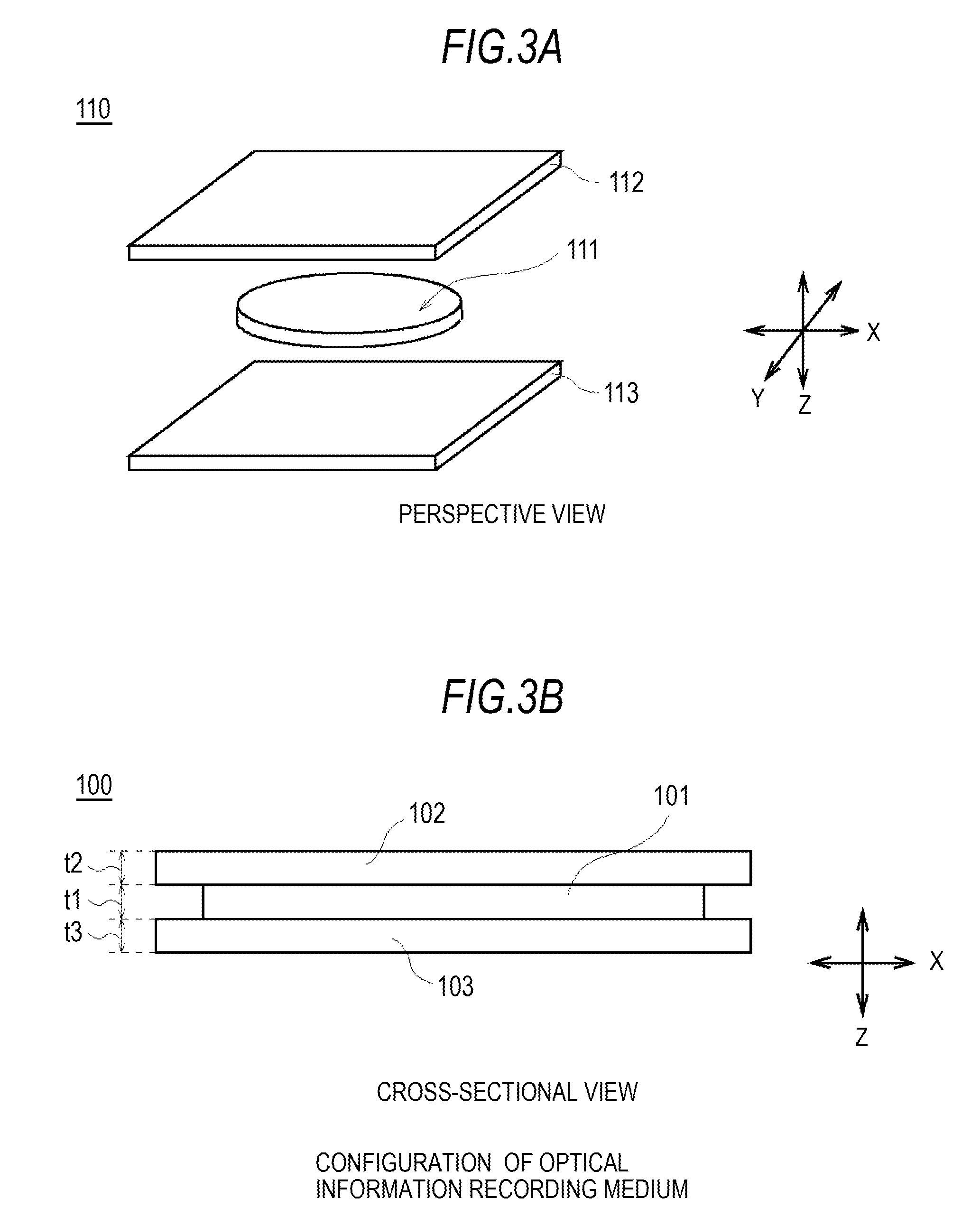
[0034]Also, as shown in a cross-sectional view of FIG. 1, the optical information recording medium 100 is configured such that a servo layer 102 is interposed from the both surfaces thereof by a recording layer 101 for recording information and a substrate 103. A thickness t1 of the recording layer 101 and a thickness t3 of the substrate 103 are each properly chosen so as to fall within the range of from 0.05 mm to 1.15 mm.

[0035]The substrate 103 is made of a material of, for example, a polycarbonate, glass, etc. and co...

second embodiment

(2) Second Embodiment

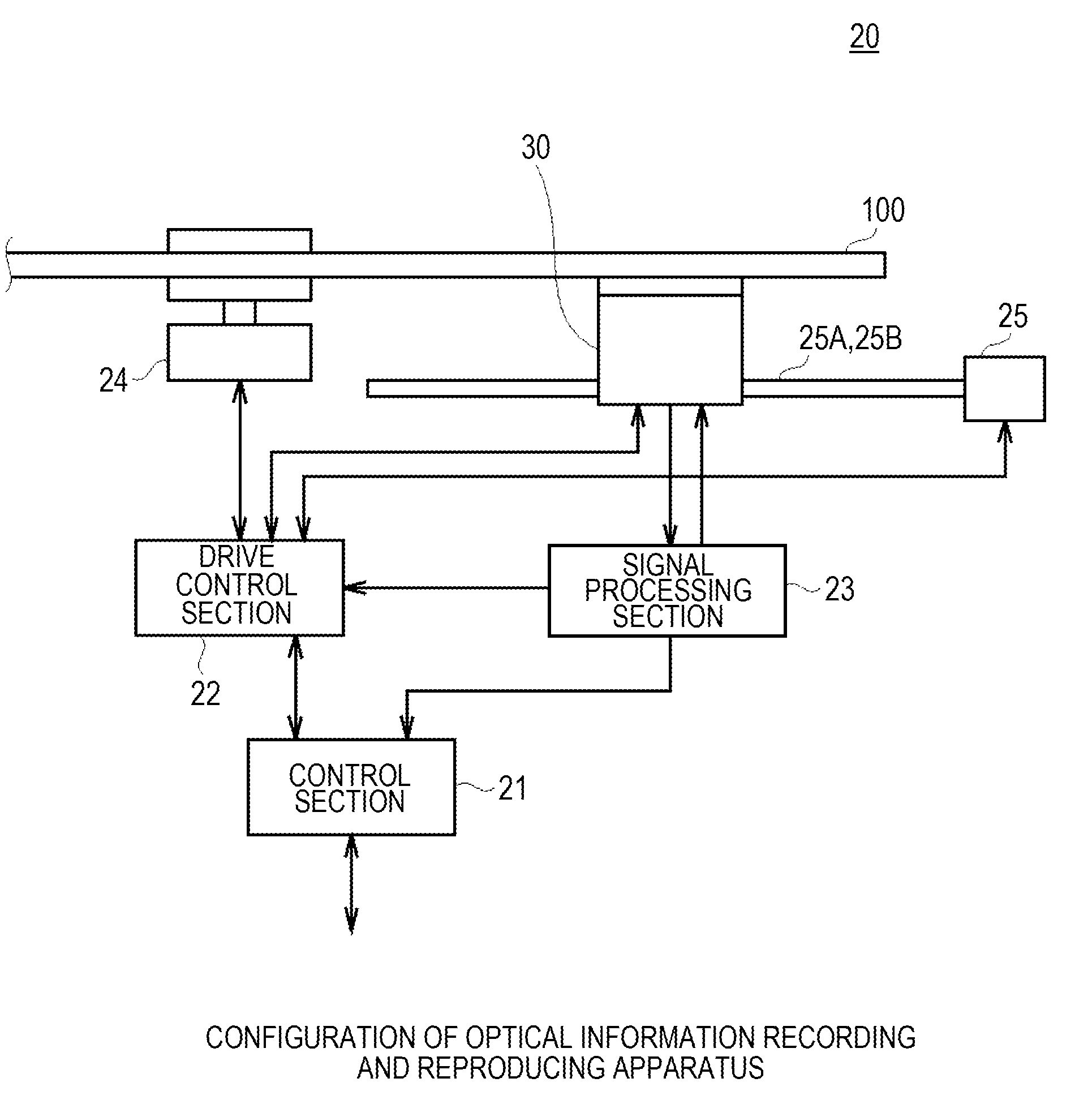
[0176]FIGS. 12 to 14 show a second embodiment, and proportions corresponding in the first embodiment as shown in FIGS. 1 to 11 are given the same symbols. The second embodiment is different from the first embodiment in points that an optical information reproducing apparatus 120 corresponding to the optical information recording and reproducing apparatus 20 performs only the reproduction of information and that the presence or absence of the recording mark RM is detected on the basis of the transmitted light beam LMo having transmitted through an optical information recording medium 200 corresponding to the optical information recording medium 100. A configuration as the optical information reproducing apparatus 120 is the same as in the optical information recording and reproducing apparatus 20, and therefore, its explanation is omitted.

(2-1) Configuration of Optical Information Recording Medium

[0177]As shown in FIG. 12, the optical information recording medium...


PUM


Abstract

An optical pickup includes: a light source that emits first light; an objective lens that condenses the first light and allows it to irradiate a track having formed therein a recording mark for intercepting the first light in a uniform recording layer of an optical information recording medium; and a light receiving section that receives transmitted light which has transmitted through the track.

Description

BACKGROUND OF THE INVENTION[0001]1. Field of the Invention[0002]The present invention relates to an optical pickup, an optical information reproducing apparatus and an optical information reproducing method and is desirably applied to, for example, an optical disc apparatus for reproducing information from an optical disc having a recording mark formed on a uniform recording layer.[0003]2. Description of the Related Art[0004]In optical disc apparatus, there have hitherto been widely spread conventional type optical discs having a signal recording layer, such as CD (compact disc), DVD (digital versatile disc) and Blu-ray Disc (a registered trademark; hereinafter referred to as “BD”). In such an optical disc apparatus, the information is reproduced by irradiating a desired track on which a light beam is to be irradiated in the signal recording layer (this track will be hereinafter referred to as “desired track”) with a light beam and reading reflected light thereof.[0005]In such a con...

Claims


Application Information

Patent Timeline
IPC IPC(8): G11B20/00G11B7/00
CPCG11B7/00452G11B2007/0009G11B7/0938
Inventor HAYASHIBE, KAZUYAUCHIYAMA, HIROSHIKUDO, TAKAOSUZUKI, YUSUKETANABE, NORIHIROSAITO, KIMIHIRO
Owner SONY CORP
Learn More