Stereoscopic tft-lcd with wire grid polarizer affixed to internal surfaces substrates
a technology of thin film transistors and substrates, applied in optics, instruments, electrical equipment, etc., can solve the problems of inability to view 3d images clearly, limited viewing distance, limited viewing angle, etc., and achieve the effect of reducing the fabrication process of the lcd device and reducing the fabrication cos
- Summary
- Abstract
- Description
- Claims
- Application Information
AI Technical Summary
Benefits of technology
Problems solved by technology
Method used
Image
Examples
first embodiment
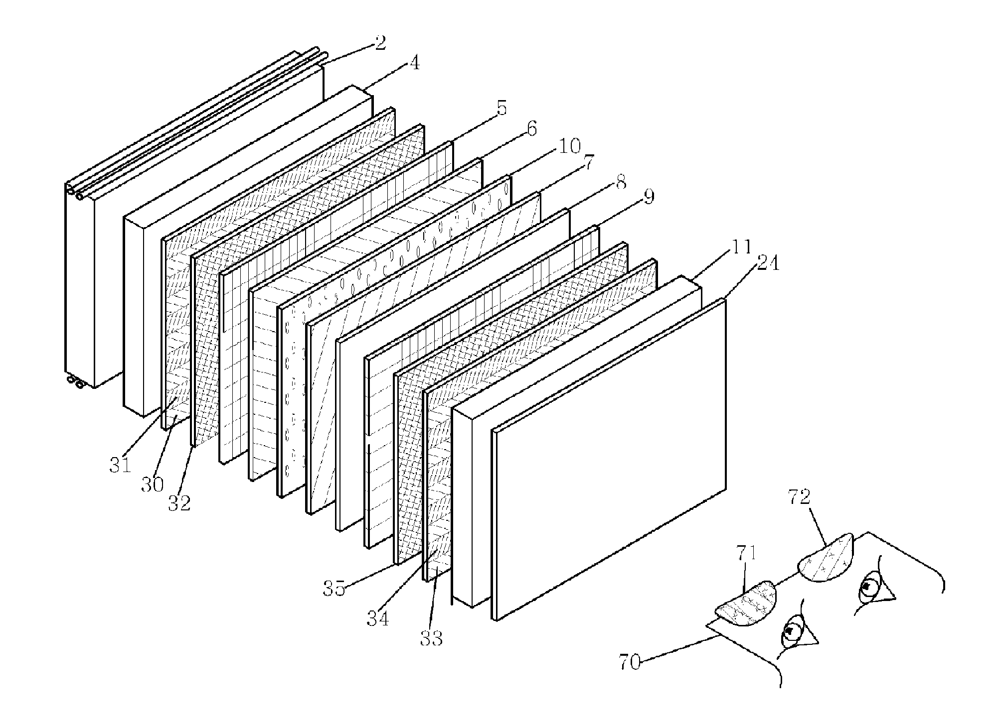
[0042]The 2D and 3D LCD device according to a first embodiment of the present invention will be described with reference to FIGS. 3 and 4. Polarizing regions are given reference numerals of 30, 31, 33, 34, 60, 61, 80 and 81 in order to recognize the regions from a polarizing film because the polarizing directions are orthogonal at 90° in a lattice shape on one plane.
[0043]As shown in FIGS. 3 and 4, in the liquid crystal device capable of displaying a 2D image and a 3D image according to the first embodiment of the present invention, a first polarizing region 30 having a polarizing direction of 0° or 45° formed on a plane of the first transparent substrate aligned on a front surface of the backlight unit 2 and a second polarizing region 31 that has a polarizing direction of 90° or 135° are aligned in an orthogonal structure. A first insulation layer 32 is aligned at a front surface of the first polarizing region 30 and the second polarizing region 31. A first transparent electrode 5 ...
second embodiment
[0052]The 2D and 3D liquid crystal display device according to the second embodiment of the present invention will be described. FIG. 6 is a view of the second embodiment, and FIG. 7 is a cross sectional view of FIG. 6.
[0053]As shown in FIG. 6, a part of the LCD device capable of displaying 2D and 3D images according to the second embodiment of the present invention is changed as compared with the first embodiment of the present invention. The above changes will be described in detail.
[0054]As shown in FIG. 6, in the LCD device capable of displaying 2D and 3D images according to the second embodiment of the present invention, a third polarizing film 52 formed of straight line polarizing films on its entire surface is disposed at the front surface of the backlight unit 2. The second ½ phase retardation film 50 and the transparent unit 51 are disposed at the front surface of the first transparent substrate 4 with a certain width and distance. Next, the first insulation layer 32 is dis...
third embodiment
[0060]FIG. 8 is a view of the third embodiment of the present invention, and FIG. 9 is a cross sectional view of FIG. 8. As shown in FIG. 8, the construction of the third embodiment of the present invention is similar with the second embodiment of the present invention except for a ¼ phase retardation film 68 that is additionally provided in this embodiment. In more detail, the light from the backlight unit 2 is changed to straight line polarizing light having 90° or 135° polarizing direction while transmitting the third polarizing film 52 formed of straight line polarizing films.
[0061]The light transmitted the transparent unit 51 disposed at the front surface of the first transparent substrate 4 is changed to straight line polarizing light having a 90° rotated polarizing direction while transmitting the liquid crystal layer 10. Thereafter, the light transmits the fourth polarizing region 34 having a 0° or 45° polarizing direction. Next, the polarized light transmits the ¼ phase ret...
PUM
| Property | Measurement | Unit |
|---|---|---|
| 3D viewing angle | aaaaa | aaaaa |
| orthogonal angle | aaaaa | aaaaa |
| angle | aaaaa | aaaaa |
Abstract
Description
Claims
Application Information
 - R&D
- Intellectual Property
- Life Sciences
- Materials
- Tech Scout
- Unparalleled Data Quality
- Higher Quality Content
- 60% Fewer Hallucinations
Browse by: Latest US Patents, China's latest patents, Technical Efficacy Thesaurus, Application Domain, Technology Topic, Popular Technical Reports.
© 2025 PatSnap. All rights reserved.Legal|Privacy policy|Modern Slavery Act Transparency Statement|Sitemap|About US| Contact US: help@patsnap.com


