
Illumination system and method with efficient polarization recovery

Inactive Publication Date: 2009-12-17
VIDEO DISPLAY CORP
View PDF13 Cites 46 Cited by
  • Summary
  • Abstract
  • Description
  • Claims
  • Application Information

AI Technical Summary

Benefits of technology

[0024]The present invention provides such a polarization-recovery illumination system. Similar to Holman, polarization recovery in the illumination system of the invention entails utilizing quarter-wave light retardation to convert linearly polarized light to circularly polarized light, light reflection to invert the handedness of circularly polarized light, and quarter-wave light retardation to convert circularly polarized light to linearly polarized light. Different from Holman, the present illumination system employs light collimation to achieve highly efficient polarization recovery. The polarization-recovery illumination system of the invention also preferably uses light integration to achieve highly uniform light illumination.
[0028]After being collimated by the collimator, the circularly polarized light of the second handedness is transmitted forward through the retardation plate and thereby converted into linearly polarized light of the first linear polarization type. The polarizer then transmits the linearly polarized light of the first linear polarization type to complete the polarization recovery process.
[0029]Importantly, the polarization recovery is done without increasing the étendue. Small light absorption losses invariably occur in the illumination system of the invention. However, largely all of the non-absorbed backward-reflected light reaches the light reflector of the light source and is reflected forward. By combining collimation with polarization recovery in the preceding way, the present illumination system efficiently utilizes the light provided by the light source.
[0033]In short, the illumination system of the invention achieves highly efficient polarization recovery without increase in the system étendue. The illumination is highly uniform. By using a high-brightness LED in the light source, the system brightness is quite high, thereby making the present illumination system particularly attractive for use in LCD light projectors. The polarization-recovery components, i.e., the reflective polarizer and the quarter-wave retardation plate, in the illumination system of the invention are considerably less expensive than PBS prism arrays used in some conventional polarization-recovery illumination systems. Consequently, the present polarization-recovery illumination system is considerably less costly than conventional prism-array-based polarization-recovery illumination systems. The invention provides a substantial advance over the prior art.

Problems solved by technology

Some transmission loss invariably occurs due to light absorption in the polarizer.
Consequently, the total light provided by the polarization-recovery illumination systems of these two patents is not efficiently utilized.
A disadvantage of PLCs is that they are very expensive.
Also, few companies in the world have the capability to manufacture them.
However, the typical operational lifetime of these lamps is only several thousand hours.
Another problem is that the lamps emit significant amount of infrared light, thus increasing the cost for heat dissipation.
As a result, the polarization-recovery efficiency of Holman's illumination system is relatively low.

Method used


Image

  • Illumination system and method with efficient polarization recovery
  • Illumination system and method with efficient polarization recovery
  • Illumination system and method with efficient polarization recovery

Examples


Embodiment Construction

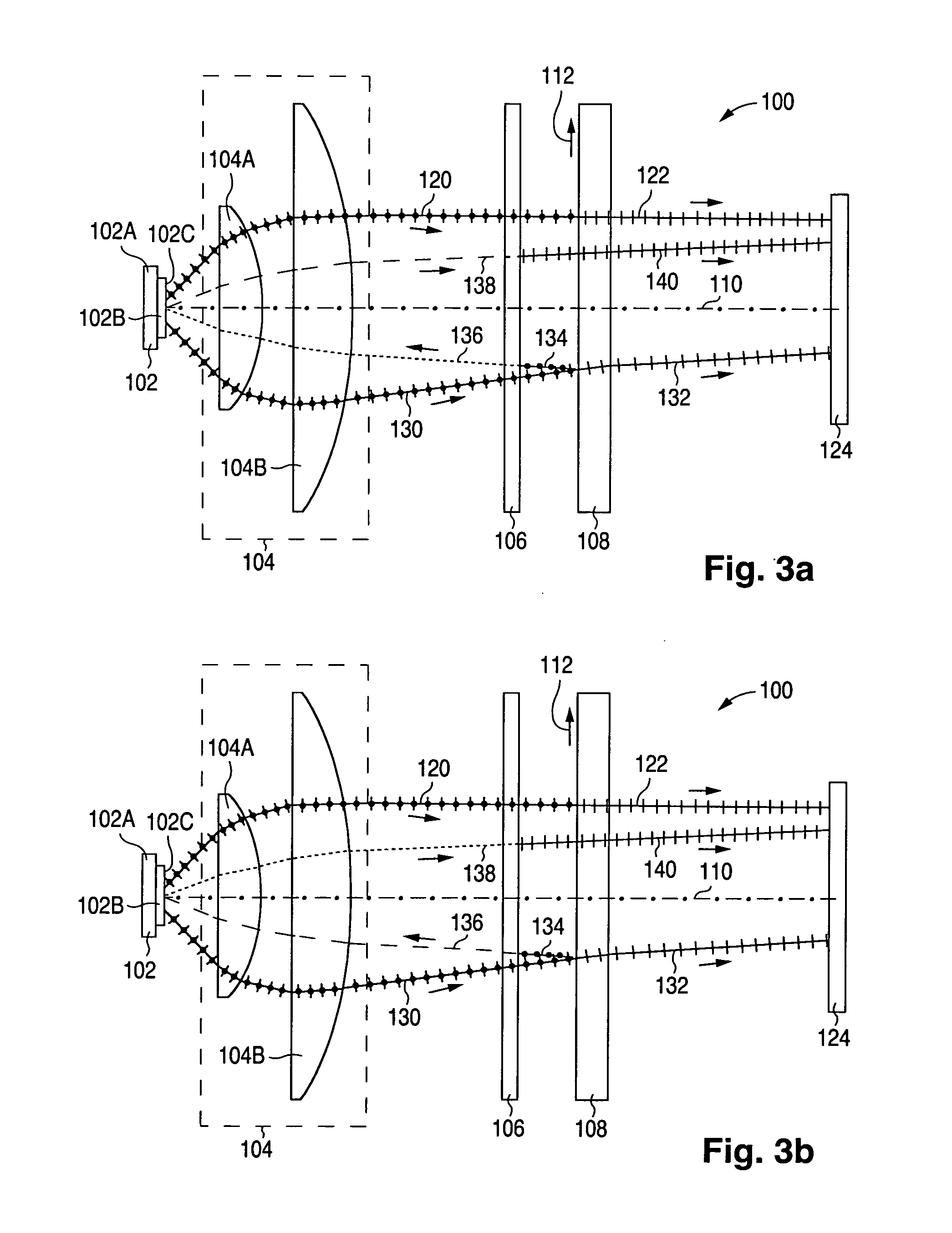
[0045]FIG. 3a illustrates a polarization-recovery illumination system 100 configured in accordance with the invention for providing linearly polarized light. Illumination system 100 consists of a light-reflective light source 102, a light collimator 104, a quarter-wave retardation plate 106, and a light-reflective linear polarizer 108 positioned sequentially along a system optical axis 110 as shown in FIG. 3a. In particular, collimator 104 is situated in front of light source 102, retardation plate 106 is situated in front of collimator 104, and polarizer 108 is situated in front of retardation plate 106.

[0046]Light source 102, which has high brightness and high luminous output, consists of a substrate 102A and a light emitter 102B having a light-reflective surface 102C which serves as a light reflector. Light emitter 102B, which is mounted on substrate 102A, emits unpolarized visible light that travels away from substrate 102A. Light reflector 102C is mounted on substrate 102A. Lig...


PUM


Abstract

Light provided by a light-reflective light source (102) in an illumination system having polarization recovery is collimated by a collimator (104) and transmitted through a quarter-wave retardation plate (106) to produce light having orthogonal linearly polarized components of first and second linear polarization types. A light-reflective linear polarizer (108) largely transmits the first-linear-polarization-type component and reflects the second-linear-polarization-type component which is then largely converted by the retardation plate into circularly polarized light of a first handedness and directed by the collimator to the light source to be reflected forward and converted into circularly polarized light of an opposite second handedness. The circularly polarized light of the second handedness is largely collimated by the collimator, converted by the retardation plate into linearly polarized light of the first polarization type, and transmitted through the polarizer to complete the polarization recovery. A light integrator (160 or 170) causes partial fluxes of composite light collimated by the collimator and transmitted through the retardation plate and polarizer to be mixed so as to make the light illumination more uniform.

Description

FIELD OF USE[0001]This invention relates to illumination systems and methods with polarization recovery.BACKGROUND ART[0002]A light source that supplies linearly (or plane) polarized light is needed to illuminate a liquid-crystal display (“LCD”) panel, either reflective or transmissive, such as that of an LCD light projector. In a conventional polarizing light source formed with a linear polarizer and a light source that provides unpolarized light, a maximum of one half of the unpolarized light incident on the polarizer passes through the polarizer and is available for illumination purposes.[0003]More particularly, light is characterized by an electric field having an electric-field vector. Unpolarized light orthogonally incident on a linear polarizer can be divided into two components having their electric field vectors respectively parallel and perpendicular to the polarization axis of the polarizer. The polarizer only transmits the light component whose electric-field vector is p...

Claims


Application Information

Patent Timeline
IPC IPC(8): G02F1/1335G02B27/18
CPCG02B27/283G02F1/133536H04N9/3197H04N9/3105H04N9/3167G02F1/133603
Inventor VIDAL, MARCIALLI, HAIZHANGYUN, ZHISHENG
Owner VIDEO DISPLAY CORP
Learn More