Intelligent Vehicle Safety Restraint System

Inactive Publication Date: 2009-12-17
MILLENWORKS
View PDF27 Cites 17 Cited by
  • Summary
  • Abstract
  • Description
  • Claims
  • Application Information

AI Technical Summary

Benefits of technology

[0010]Preferably, the active restraint includes two lap belts (also known as straps or webbing), two shoulder belts, and a tie-down strap attached to a rotary buckle. Attached to each lap and shoulder strap is a webbing retractor with an integral pyrotechnic pretensioner, a reversible pretensioner, and a spool position encoder. The reversible and resettable nature of the reversible pretensioners greatly increase the ability of the restraint to keep the occupant in a safe and survivable orientation without interfering with their duties. The pyrotechnic pretensioner allows for quicker retraction and therefore can be activated after a crash has begun. In this respect, the combined use of both the reversible electric pretensioner and the pyrotechnic pretensioner provides the best attributes of both devices in a single retractor.
[0012]When a shoulder strap is extended significantly beyond the baseline position for any length of time, the occupant is reminded to sit up straight by a gentle, haptic, “out of position” tug on the shoulder strap caused by momentarily energizing the retractor's reversible pretensioning motor. If the CRM's predictive algorithms determine that the vehicle is maneuvering aggressively or erratically, each retractor's reversible pretensioner is energized to supplement the passive spring retraction force and eliminate slack from the shoulder and lap straps. The elimination of belt slack significantly reduces occupant slump and rotation during a blast or crash event. Additionally, keeping the occupant upright and close to the seat back during aggressive maneuvers may improve his or her ability to maintain control of the vehicle.
[0014]While the shoulder strap pretensioners are effective at controlling lateral torso motion, the occupant's head can still experience enough lateral motion to cause a secondary impact with a side window or other primary structure, especially in vehicles with small cabins. To effectively control this, an active headrest is used in the preferred embodiment of this invention. To avoid limiting the occupant's field of vision during routine vehicle operation, the lateral supports are stowed in an aft or retracted position.
[0018]After the CRM determines that the vehicle is once again in stable operation, it commands the retractors to return to baseline position and the headrest to retract its lateral supports. If at any time the algorithms determine that a crash is occurring, the CRM deploys the active headrest (if it is currently stowed) and sends a firing signal to each retractor pretensioner, causing it to retract additional webbing within 50 milliseconds of activation. The quick reaction time can be especially achieved with the pyrotechnic pretensioner which is ignited by electrical energy above a threshold value. The electrical energy is stored in a capacitor bank inside the CRM and released by closing a switch.

Problems solved by technology

Unfortunately, deformable structures are less applicable to military aircraft and ground vehicles.
The large volume of vehicle controls and mission-related equipment located in the cabins of these vehicles make it impossible to surround the occupants with deformable structure.
The occupants of these vehicles are also exposed to rapid vertical accelerations which are not present in automobiles, further complicating the protection of these occupants from secondary impacts within the vehicle.
While this approach reduces spinal injuries, the vertical motion of the seat makes the occupant more likely to strike other objects within the vehicle cabin.
The occupant's body can further deviate due to maneuver loads.
This deceleration causes the occupant to move and slump in his seat.
This increases the tension on the restraint's shoulder straps, causing the webbing to pack down within the shoulder harness retractor and stretch, effectively loosening the restraint and causing the occupant's upper torso and head to rotate forward into close proximity with hard structures within the vehicle.
The slump, rotation and energy attenuation makes secondary cabin impacts more likely and, in vehicles with small cabins, can even result in the occupant's head or body protruding through the vehicle window or door.

Method used


Image

  • Intelligent Vehicle Safety Restraint System
  • Intelligent Vehicle Safety Restraint System
  • Intelligent Vehicle Safety Restraint System

Examples


Embodiment Construction

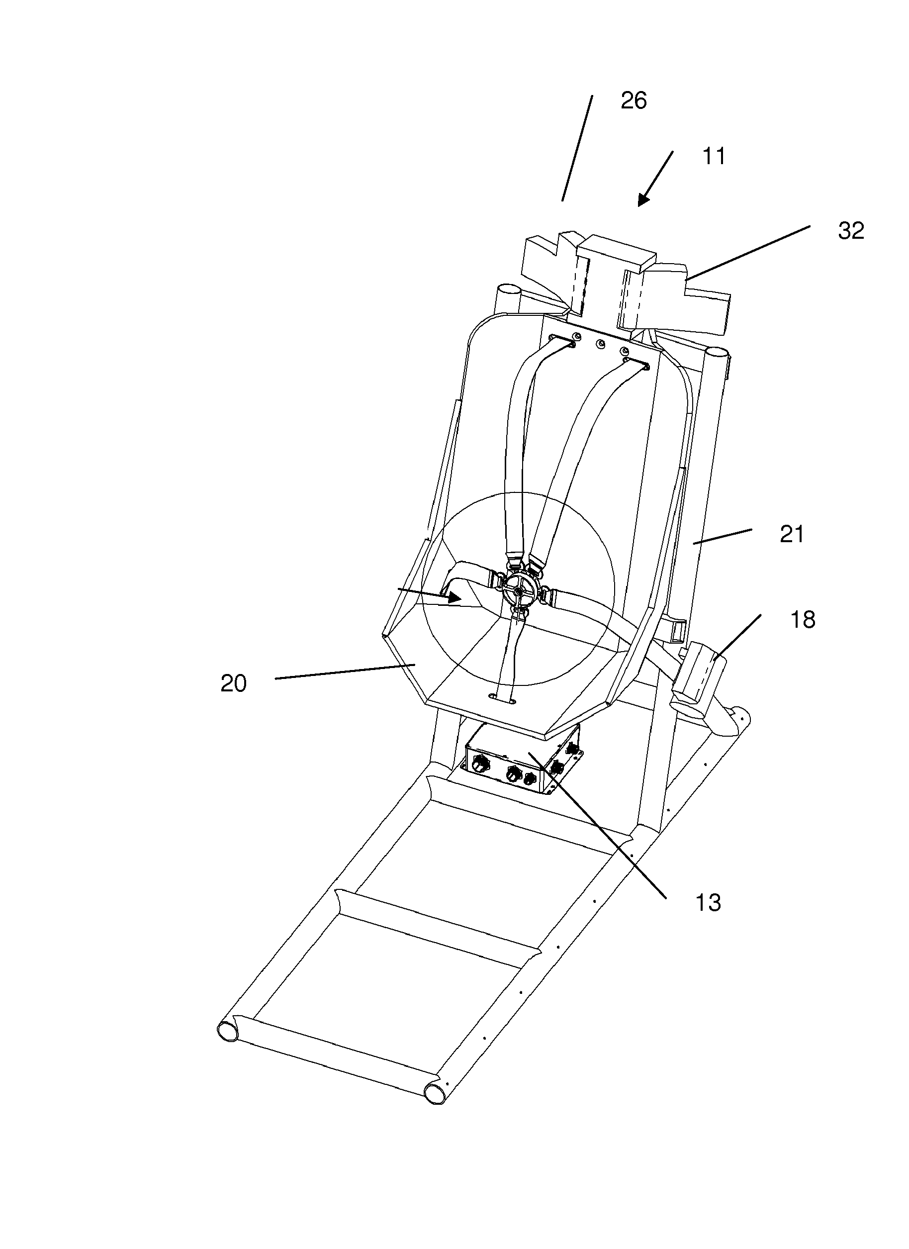
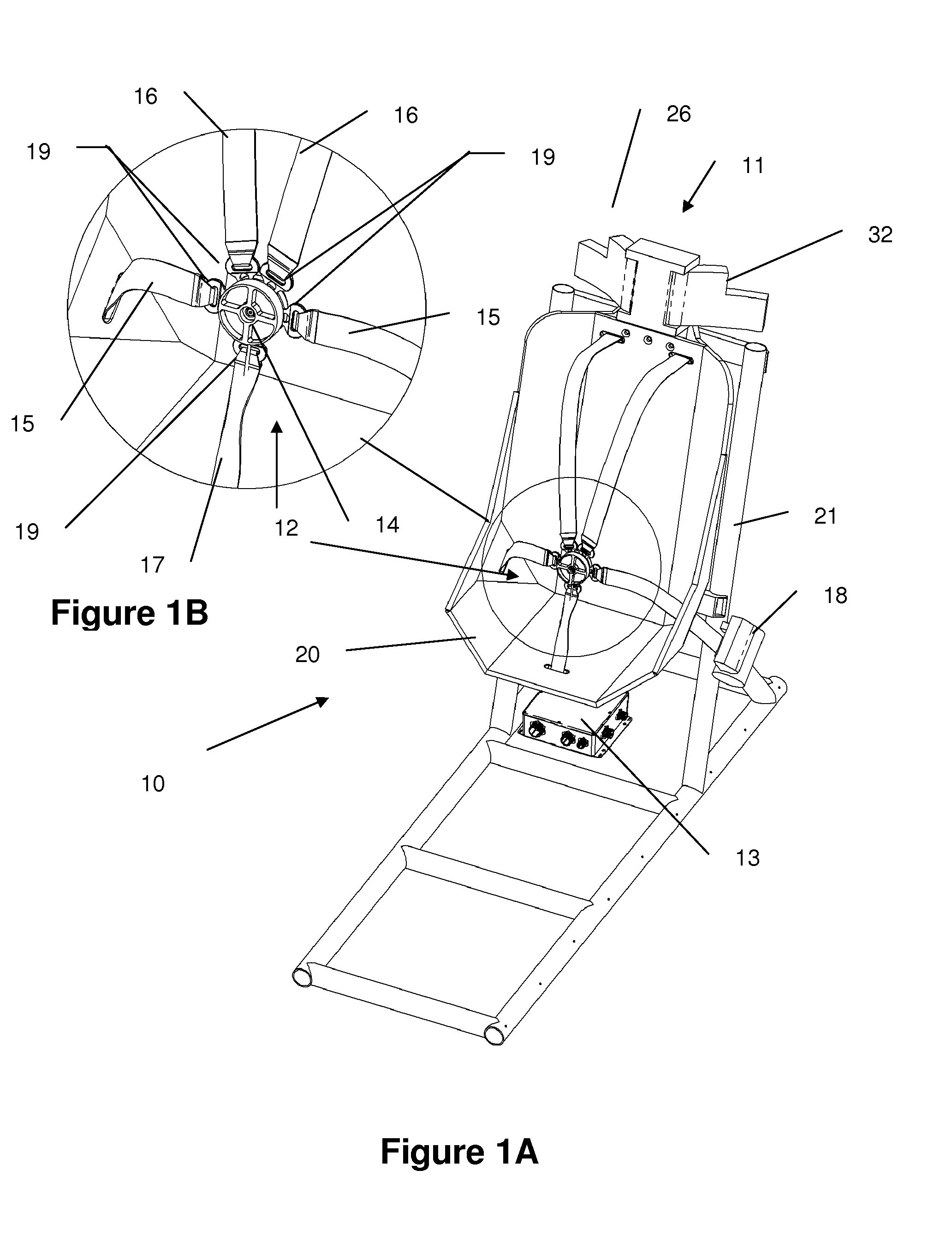
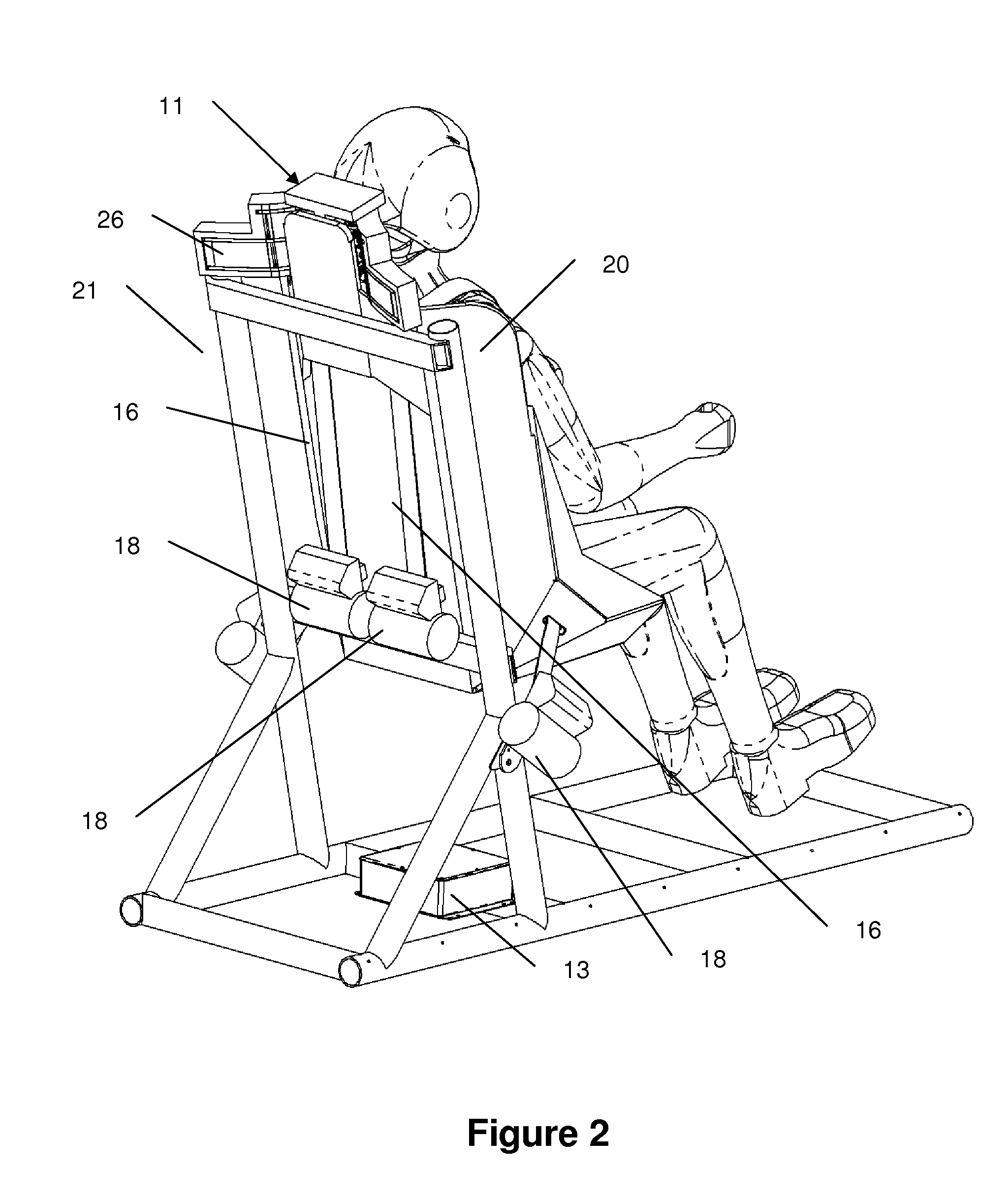
[0029]Specific embodiments of the invention will now be described with reference to the accompanying drawings. This invention may, however, be embodied in many different forms and should not be construed as limited to the embodiments set forth herein; rather, these embodiments are provided so that this disclosure will be thorough and complete, and will fully convey the scope of the invention to those skilled in the art. The terminology used in the detailed description of the embodiments illustrated in the accompanying drawings is not intended to be limiting of the invention. In the drawings, like numbers refer to like elements.

[0030]Unless otherwise defined, all terms (including technical and scientific terms) used herein have the same meaning as commonly understood by one of ordinary skill in the art to which this invention belongs. It will be further understood that terms, such as those defined in commonly used dictionaries, should be interpreted as having a meaning that is consis...


PUM


Abstract

A resettable combat vehicle restraint system prevents secondary impacts within the vehicle cabin during crash, mine blast, or rollover events by positioning the occupant within a load attenuating seat to best survive the dangerous event. The preferred embodiment of the restraint system includes a five point restraint, webbing retractors for each lap and shoulder belt with the capability for both reversible and pyrotechnic pretensioning, an active headrest, and a crash recognition module to electrically activate the pyrotechnic pretensioners and to electrically modulate the actions of the reversible pretensioning retractors and the active headrest.

Description

RELATED APPLICATIONS[0001]This application claims priority to U.S. Provisional Application Ser. No. 61 / 061,332 filed Jun. 13, 2008 entitled Resettable Safety System for Upgraded Occupant Survivability, the contents of which are incorporated in their entirety herein.BACKGROUND OF THE INVENTION[0002]The present invention generally relates to the protection of military vehicle occupants from the high forces encountered during a crash event, specifically from secondary impacts within the vehicle.[0003]In automobiles, crash energy mitigation has focused on protection of occupants through passive occupant restraints and by limiting secondary impact forces using load-attenuating deformable structures such as padded dashboards, collapsible steering columns, and airbags. This approach has dramatically reduced both serious and fatal injuries in the modern automobile.[0004]Unfortunately, deformable structures are less applicable to military aircraft and ground vehicles. The large volume of veh...

Claims


Application Information

Patent Timeline
IPC IPC(8): B60R22/46
CPCB60N2/4805B60N2/4882B60N2/4885B60R22/26B60R2022/4825B60R22/4628B60R2022/027B60R2022/4666B60R2022/469B60R22/46B60N2/888B60N2/806B60N2/885
Inventor VAN DRUFF, CHARLESCULBERTSON, CHRISTOPHER
Owner MILLENWORKS
Why Eureka
Try Eureka