
Ceiling-only dry sprinkler systems and methods for addressing a storage occupancy fire

a dry sprinkler and floor only technology, applied in watering devices, medical science, horticulture, etc., can solve the problems of difficult maintenance, inferior dry sprinkler systems to wet systems, and large volume of air that must escape or be expelled, so as to reduce the heat release from the fire event quickly, eliminate or minimize the economic disadvantages and design penalties

Active Publication Date: 2009-12-10
TYCO FIRE PRODS LP
View PDF15 Cites 10 Cited by
  • Summary
  • Abstract
  • Description
  • Claims
  • Application Information

AI Technical Summary

Benefits of technology

The patent describes a new sprinkler system for protecting fire in storage areas. The system uses a non-wet, dry pipe system that is designed to address fire events in a unique way. The system is designed to be installed without the need for penalties and can provide effective fire protection without the need for a large number of sprinklers. The system uses a minimized sprinkler operational area that is designed to surround and drown the fire, reducing the amount of water needed and minimizing the hydraulic demand on the system. The system is designed to be installed in a ceiling-only configuration, which eliminates or minimizes the need for large hydraulic design areas. Overall, the system provides effective fire protection without the need for penalties and can be designed to minimize the hydraulic demand on the system.

Problems solved by technology

Moreover, if the system is large and / or if the system is charged to a typical pressure such as 40 psig, a considerable volume of air must escape or be expelled from the open sprinkler head before the specific hydraulic imbalance is reached to open the primary water valve.
This belief has led to an industry-side perception that dry sprinkler systems are inferior to wet systems.
A problem with the in-rack sprinklers are that they may be difficult to maintain and are subject to damage from forklifts or the movement of storage pallets.
However, NFPA adds an additional penalty for dry system ceiling-only sprinkler systems by increasing the design criteria to 0.8 gpm / ft2 per 4500 ft2.
This increased area requirement is a 125% density penalty over the wet system design criteria.
Moreover, NFPA 13 provides limited ceiling-only protection in limited rack storage configurations, and otherwise require in-rack sprinklers.
Despite the apparent economic design advantage of wet systems over dry systems, certain storage configurations prohibit the use of wet systems or make them otherwise impractical.
For example, in warehouses using high rack storage, i.e. 25 ft. high storage beneath a 30 ft. high ceiling, such warehouses may be unheated and therefore susceptible to freezing conditions making wet sprinkler systems undesirable.
Freezer storage presents another environment that cannot utilize wet systems because water in the piping of the protection system located in the freezer system would freeze.
However, the use of antifreeze can raise other issues such as, for example, corrosion and leakage in the piping system.
In addition, the high viscosity of antifreeze may require increased piping size.
Moreover, propylene glycol (PG) antifreeze has been shown not to have the fire-fighting characteristics of water and in some instances has been known to momentarily accelerate fire growth.
In addition, the discharge of fluid from a given sprinkler cap result in the impingement of water droplets and / or the build up of condensation of water vapor on adjacent and unactuated sprinklers.
Despite the availability of immediate fluid delivery from each sprinkler in a wet sprinkler system, wet sprinkler systems can also experience sprinkler skipping.
Moreover, to hydraulically configure a dry system for suppression may require adequately sized piping and pumps whose costs may prove economically prohibitive as these design constraints may require hydraulically sizing the system beyond the demands already imposed by the design “penalties.”
However, in addition to the high operating pressure of 55 psi., such a system required a total of twenty-five (25) sprinkler operations actuated over a seventeen minute period.
The second fire test employed a sixty-second (60 sec.) water delay time, however such a delay time proved to be too long as the fire developed to such a severity that adequate fire control could not be achieved.

Method used


Image

  • Ceiling-only dry sprinkler systems and methods for addressing a storage occupancy fire
  • Ceiling-only dry sprinkler systems and methods for addressing a storage occupancy fire
  • Ceiling-only dry sprinkler systems and methods for addressing a storage occupancy fire

Examples


example 1

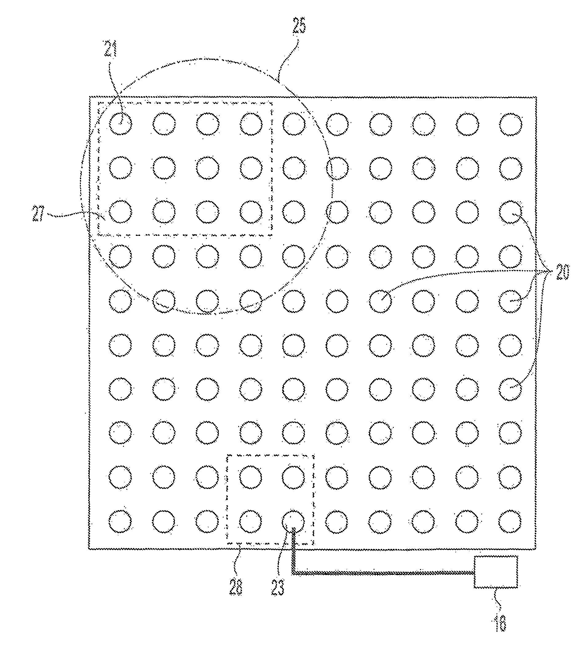
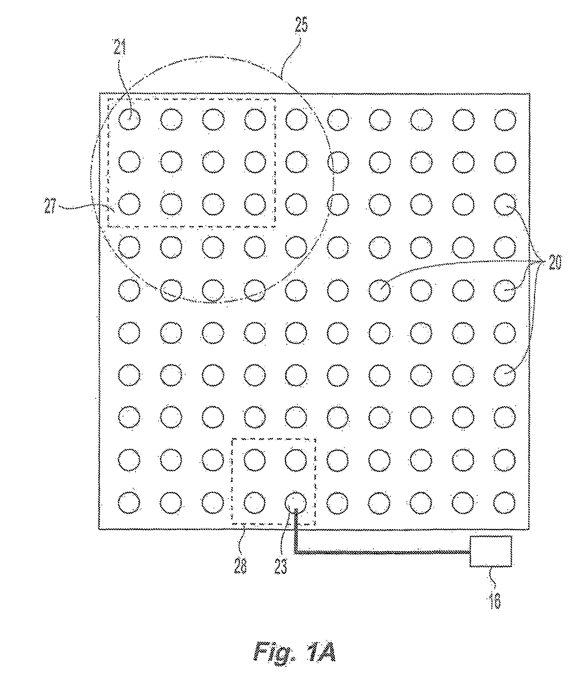
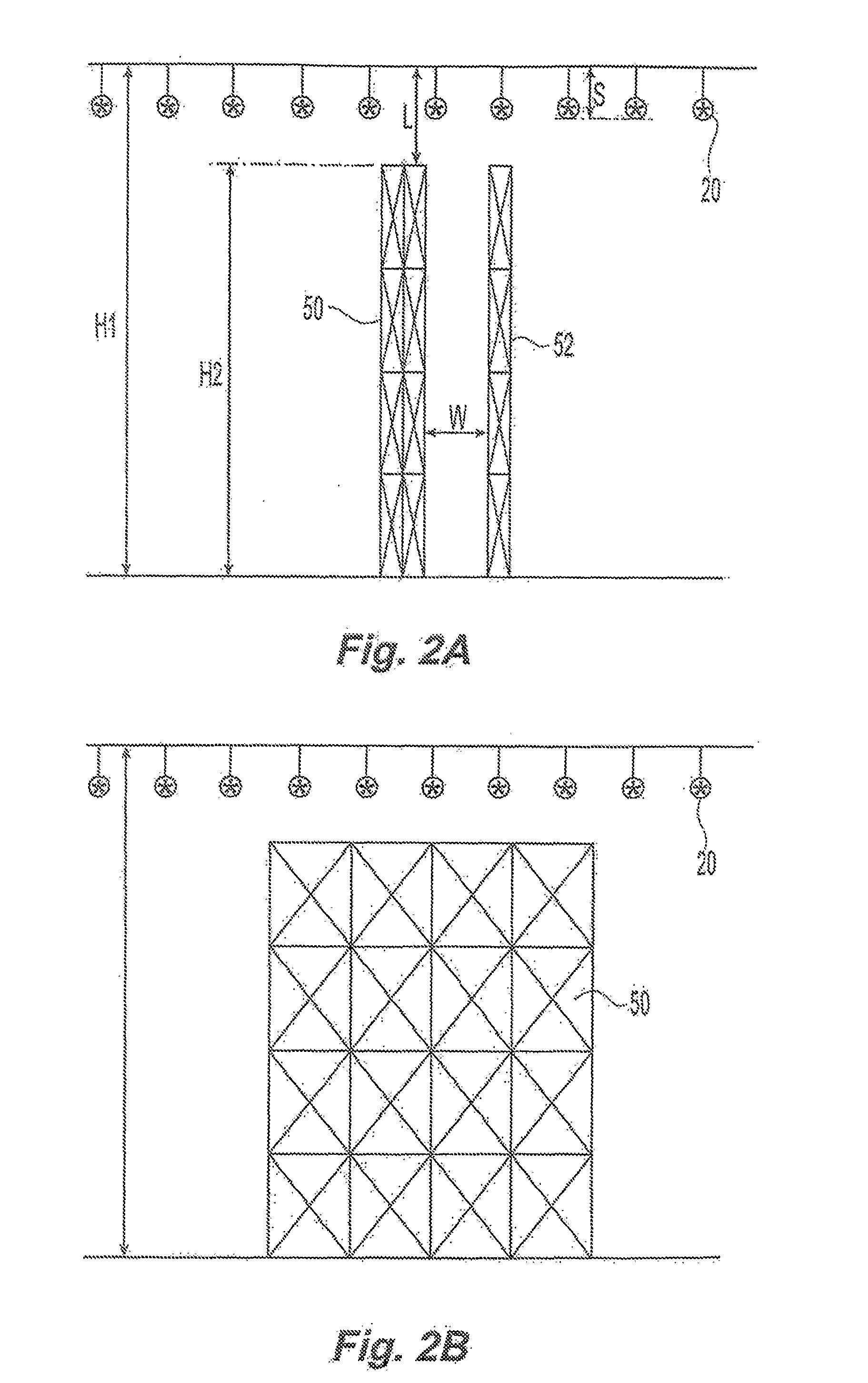
[0134]A sprinkler system 10 for the protection of Class II storage commodity was constructed as a test plant and modeled to generate the predictive heat release and sprinkler activation profiles. The test plant room measured 120 ft.×120 ft. and 54 ft. high. The test plant included a 100 ft.×100 ft. adjustable height ceiling which permitted the ceiling height of the plant to be variably set. The system parameters included Class II commodity in multiple-row rack arrangement stored to a height of about thirty-four (34 ft.) located in a storage area having a ceiling height of about forty feet (40 ft.). The dry sprinkler system 10 included one hundred 16.8 K-factor upright specific application storage sprinklers 20 having a nominal RTI of 190 (ft-sec.)1 / 2 and a thermal rating of 286° F. on ten foot by ten foot spacing. The sprinkler system 10 was located about seven inches (7 in.) beneath the ceiling and supplied with a looped piping system. The sprinkler system 10 was configured to prov...

example 2

[0141]In a second fire test, a sprinkler system 10 for the protection of Class III storage commodity was modeled and tested in the test plant room. The system parameters included Class III commodity in a double-row rack arrangement stored to a height of about thirty feet (30 ft.) located in a storage area having a ceiling height of about thirty-five feet (35 ft.). The dry sprinkler system 10 included one hundred 16.8 K-factor upright specific application storage sprinklers having a nominal RTI of 190 (ft-sec.)1 / 2 and a thermal rating of 286° F. on ten foot by ten foot (10 ft.×10 ft.) spacing. The sprinkler system was located about seven inches (7 in.) beneath the ceiling.

[0142]The system 10 was modeled as normalized to develop a predictive heat release and sprinkler activation profile as seen in FIG. 6. From the predictive profiles, eighty percept Of the maximum sprinkler operational area 27, totaling about sixteen (16) sprinklers was predicted to occur following a maximum fluid del...

example 3

[0148]In a third fire test, a sprinkler system 10 for the protection of Class III storage commodity was modeled and tested in the test plant room. The system parameters included Class III commodity in a double-row rack arrangement stored to a height of about forty feet (40 ft.) located in a storage area having a ceiling height of about forty-three feet (43 ft.). The dry sprinkler system 10 included one hundred 16.8 K-factor upright specific application storage sprinklers having a nominal RTI of 190 (ft-sec.)1 / 2 and a thermal rating of 286° F. on ten foot by ten foot (10 ft.×10 ft.) spacing. The sprinkler system was located about seven inches (7 in.) beneath the ceiling.

[0149]The test plant was modeled as normalized to develop a predictive heat release and sprinkler activation profile as seen in FIG. 7. From the predictive profiles, eighty percent of the specified maximum sprinkler operational area 27, totaling of about sixteen (16) sprinklers, was predicted to occur following a maxi...


PUM


Abstract

A ceiling-only dry sprinkler system configured to address a storage occupancy fire event with a sprinkler operational area sufficient in size to surround and drown fire. The system and method preferably provide for the surround and effect by activating one or more initial sprinklers, delaying fluid flow to the initial activated sprinklers for a defined delay period to permit the thermal activation of a subsequent-one or more sprinklers so as. to form the preferred sprinkler Operational area. The sprinklers of the operational area are preferably: configured so as to provider sufficient fluid volume and cooling to address the fire event with a surround and drown configuration, the defined delay period is of a defined period having a maximum and a minimum. The preferred sprinkler system is adapted for fire protection of storage commodities and provides a ceiling only system that eliminates or otherwise minimizes the economic disadvantage and design penalties current dry sprinkler system design.

Description

PRIORITY DATA AND INCORPORATION BY REFERENCE[0001]This application claims the benefit of priority to the following: (i) U.S. Provisional Patent Application No. 60 / 728,734, filed Oct. 21, 2005; (ii) U.S. Provisional Patent Application No. 60 / 818,312, filed on Jul. 5, 2006 (iii) U.S. Provisional Patent Application no. 60 / 744,644, filed on Feb. 21, 2006, each of which are incorporated by reference in their entirety. Further incorporated herein in their entirety by reference are the following: (i) PCT International Patent Application filed on Oct. 3, 2006 entitled, “System and Method for Evaluation of Fluid Flow in a Piping System,” having Docket Number S-FB-0091WO (73434-029WO) which claims priority to (ii) U.S. Provisional Patent Application 60 / 722,401 filed on Oct. 3, 2005; (iii) U.S. patent application Ser. No. 10 / 942,817 filed Sep. 17, 2004, published as U.S. patent Publication No. 2005 / 0216242, and entitled “System and Method For Evaluation of Fluid Flow in a Piping System; ” (iv)...

Claims


Application Information

Patent Timeline
Patent Type & Authority Applications(United States)
IPC IPC(8): A62C35/62A62C35/64B05B17/04
CPCA62C3/002A62C35/68A62C35/645A62C35/58A62C37/08A62C35/60A62C35/62
Inventor GOLINVEAUX, JAMES E.LEBLANC, DAVID J.
Owner TYCO FIRE PRODS LP
Learn More