
Scheduling of Multiple Tasks in a System Including Multiple Computing Elements

a computing element and task scheduling technology, applied in multi-programming arrangements, program control, instruments, etc., can solve the problem that the local memory of a computing element is typically insufficient capacity for storing

Inactive Publication Date: 2009-12-03
MOBILEYE TECH
View PDF6 Cites 55 Cited by
  • Summary
  • Abstract
  • Description
  • Claims
  • Application Information

AI Technical Summary

Benefits of technology

[0009]The local memory of a computing element typically has insufficient capacity for storing simultaneously all the task descriptors of the task queue. Access to, and the execution of, the task queue are performed portion-by-portion. When a CE executes one or more tasks of the task queue, the CE then stores the generated execution results in the locations of the local memory which were just previously used to store the task descriptor just executed. When all the tasks within the portion of the task queue brought into the CE have been executed, the local DMA unit then transfers out all the corresponding results to the system memory in an area indicated by the task queue information result queue pointer.
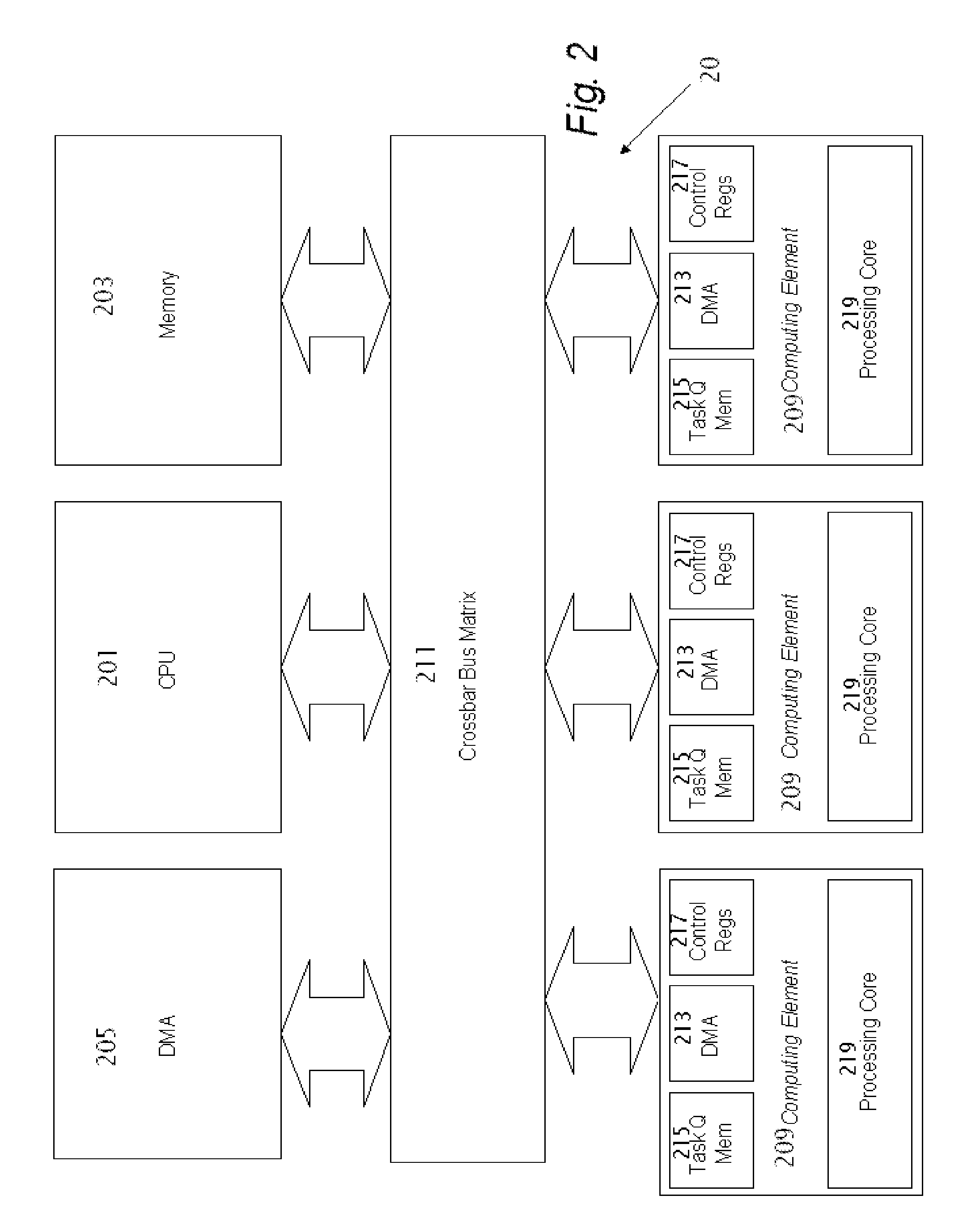
[0010]When the task queue is part of a batch of task queues for execution by the computing element, the task queue information preferably includes a pointer to the next queue in the batch. Typically, each of the computing elements have attached control registers. The control registers are loaded with the task queue information regarding the task queue. The task queue information is preferably organized in a data structure which preferably contains: (i) the number of tasks in the task queue, and (ii) a pointer in system memory to where the task descriptors reside. The task queue information preferably also includes: (iii) a results queue pointer which points to a location in system memory to store results of the execution.
[0011]According to another aspect of the present invention, there is provided a system including a central processing unit (CPU), a system memory operatively attached to and accessed by the CPU, and computing ele...

Problems solved by technology

The local memory of a computing element typically has insufficient capacity for storing simultaneously all the task descriptors of the task queue.

Method used


Image

  • Scheduling of Multiple Tasks in a System Including Multiple Computing Elements
  • Scheduling of Multiple Tasks in a System Including Multiple Computing Elements
  • Scheduling of Multiple Tasks in a System Including Multiple Computing Elements

Examples


Embodiment Construction

[0027]Reference will now be made in detail to embodiments of the present invention, examples of which are illustrated in the accompanying drawings, wherein like reference numerals refer to the like elements throughout. The embodiments are described below to explain the present invention by referring to the figures.

[0028]It should be noted, that although the discussion herein relates to a system including multiple processors, e.g. CPU and computational elements on a single die or chip, the present invention may, by non-limiting example, alternatively be configured as well using multiple processors on different dies packaged together in a single package or discrete processors mounted on a single printed circuit board.

[0029]Before explaining embodiments of the invention in detail, it is to be understood that the invention is not limited in its application to the details of design and the arrangement of the components set forth in the following description or illustrated in the drawings...


PUM


Abstract

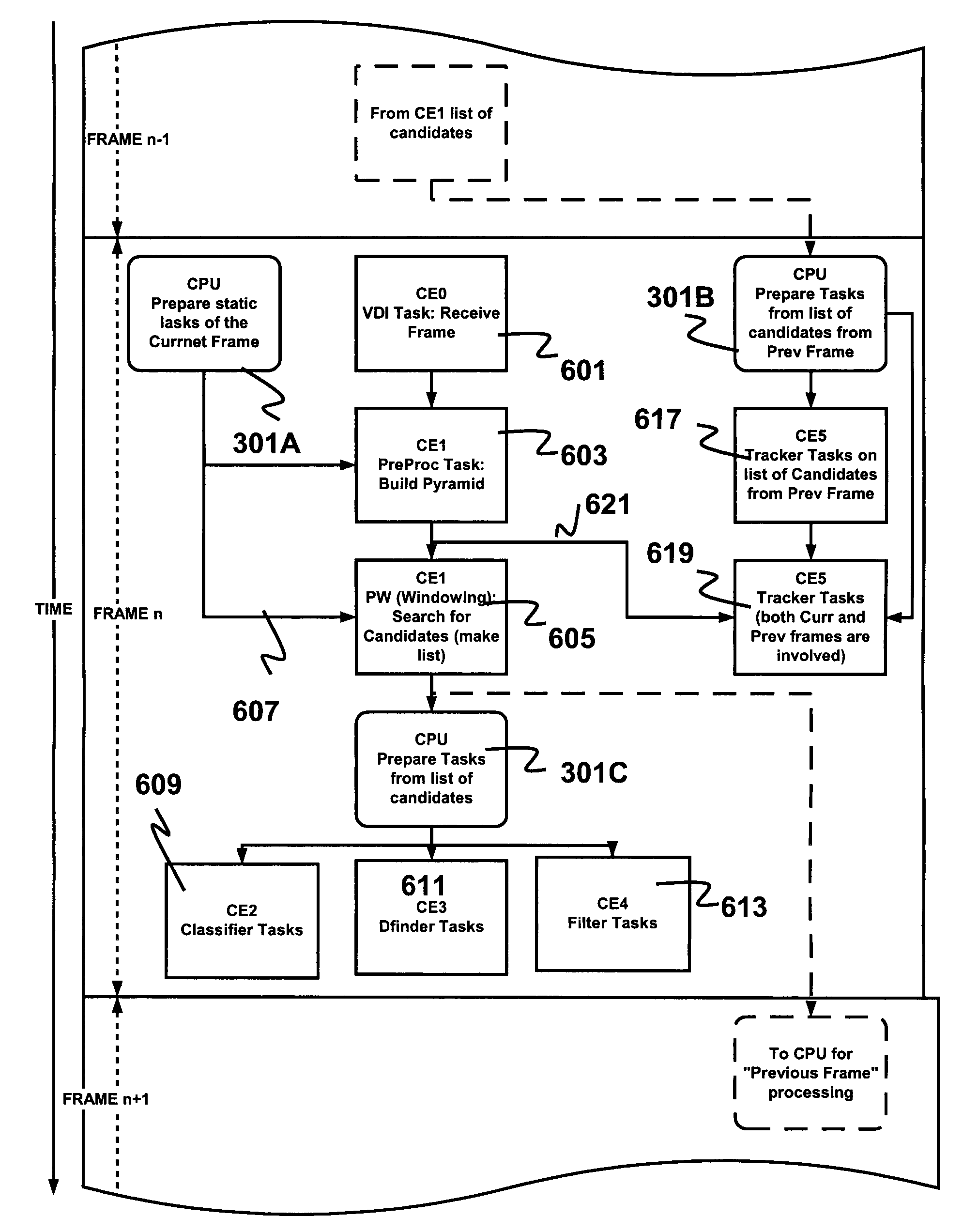
A method for controlling parallel process flow in a system including a central processing unit (CPU) attached to and accessing system memory, and multiple computing elements. The computing elements (CEs) each include a computational core, local memory and a local direct memory access (DMA) unit. The CPU stores in the system memory multiple task queues in a one-to-one correspondence with the computing elements. Each task queue, which includes multiple task descriptors, specifies a sequence of tasks for execution by the corresponding computing element. Upon programming the computing element with task queue information of the task queue, the task descriptors of the task queue in system memory are accessed. The task descriptors of the task queue are stored in the local memory of the computing element. The accessing and the storing of the data by the CEs is performed using the local DMA unit. When the tasks of the task queue are executed by the computing element, the execution is typically performed in parallel by at least two of the computing elements. The CPU is interrupted respectively by the computing elements only upon their fully executing the tasks of their respective task queues.

Description

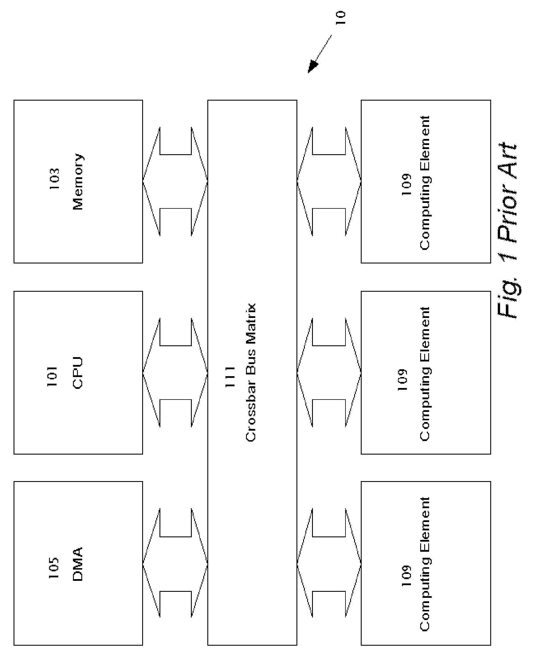
FIELD AND BACKGROUND[0001]The present invention relates to a digital signal processing system including a central processing unit (CPU) and multiple computing elements performing parallel processing and a method of controlling the flow of the parallel processing by the multiple computing elements.[0002]Reference is now made to FIG. 1 which illustrates a conventional system 10 including a CPU 101 and multiple computing elements 109 connected by a crossbar matrix 111. System 10 includes shared memory 103 and a shared direct memory access (DMA) unit 105 for accessing memory 103. Alternatively, conventional system 10 may be configured with a bus and bus arbiter instead of crossbar matrix 111. When CPU 101 runs a task on one of computing elements 109, CPU 101 transfers to computing element 109 a task descriptor including various parameters specifying the task, and then instructs computing element 109 to start processing the task. CPU 101 similarly transfers task descriptors to other comp...

Claims


Application Information

Patent Timeline
IPC IPC(8): G06F9/44
CPCG06F2209/483G06F9/4881
Inventor NAVON, MOISRUSHINEK, ELCHANANSIXOU, EMMANUELPANN, ARKADYKREININ, YOSSI
Owner MOBILEYE TECH
Learn More