Microscope
a microscope and microscope technology, applied in the field of microscope technology, can solve problems such as difficulty in uniform irradiation of the irradiation area
- Summary
- Abstract
- Description
- Claims
- Application Information
AI Technical Summary
Benefits of technology
Problems solved by technology
Method used
Image

Examples
first embodiment
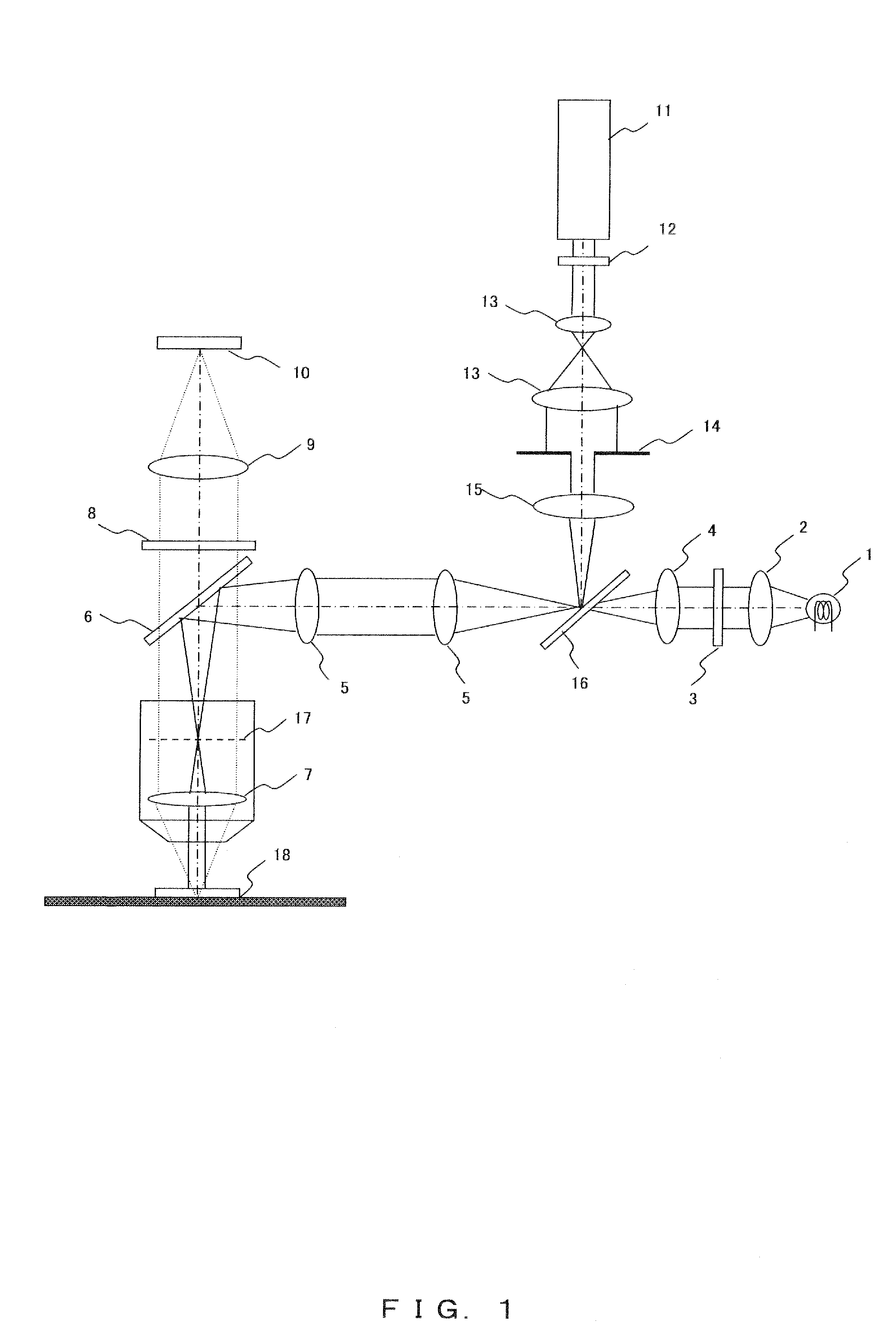
[0019]FIG. 1 is a schematic diagram of a configuration of an upright microscope with coaxial epi-illumination according to the present embodiment.
[0020]The upright microscope of FIG. 1 includes an epi-illumination unit, an observation optical system, and a laser introduction optical system.
[0021]The epi-illumination unit includes a light source 1, a collimator lens 2, an exciter filter 3, an illumination light condensing lens 4, and an epi-illumination projecting tube optical system 5. An illumination light path formed by the epi-illumination unit is coupled to an observation light path at a dichroic mirror 6.
[0022]The observation optical system includes an objective lens 7, a barrier filter 8, a tube lens 9, and an imaging device 10. The observation optical system may be configured for visual observations by including an eye piece unit or an eye piece instead of the imaging device 10.
[0023]The laser introduction optical system includes a laser light source 11, a shutter 12, a beam ...
second embodiment
[0032]FIG. 3 is a schematic diagram illustrating a configuration of a laser scanning microscope according to the present embodiment. The present configuration includes two scanning units in which a scanning unit for observation and a scanning unit for stimulation are independently provided.
[0033]The microscope of FIG. 3 includes an observation-use laser light source 19, an observation-use shutter 20, an observation-use scanning unit 21, an observation-use pupil, projection lens 22, a tube lens 23, an objective lens 7, an excitation light-use dichroic mirror 24, a confocal lens 25, a confocal pinhole 26, a barrier filter 27, and a photodetector 28, on an observation-use light path. Here, a galvanomirror, a photoelectric deflection element or the like may be used as the observation-use scanning unit 21.
[0034]The microscope also includes a stimulation-use laser light source 29, a stimulation-use shutter 30, a beam diameter changing optical system 31, a tunable stop 32, a laser light co...
third embodiment
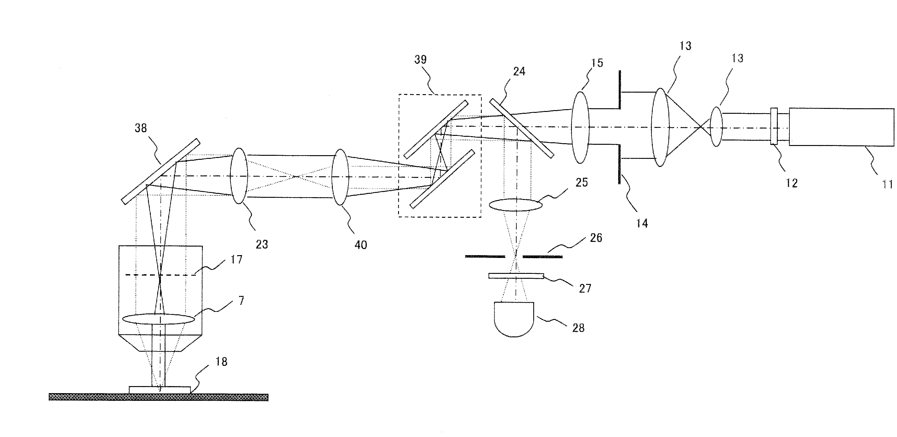
[0047]FIG. 4 is a schematic diagram illustrating a configuration of a laser scanning microscope according to the present embodiment.
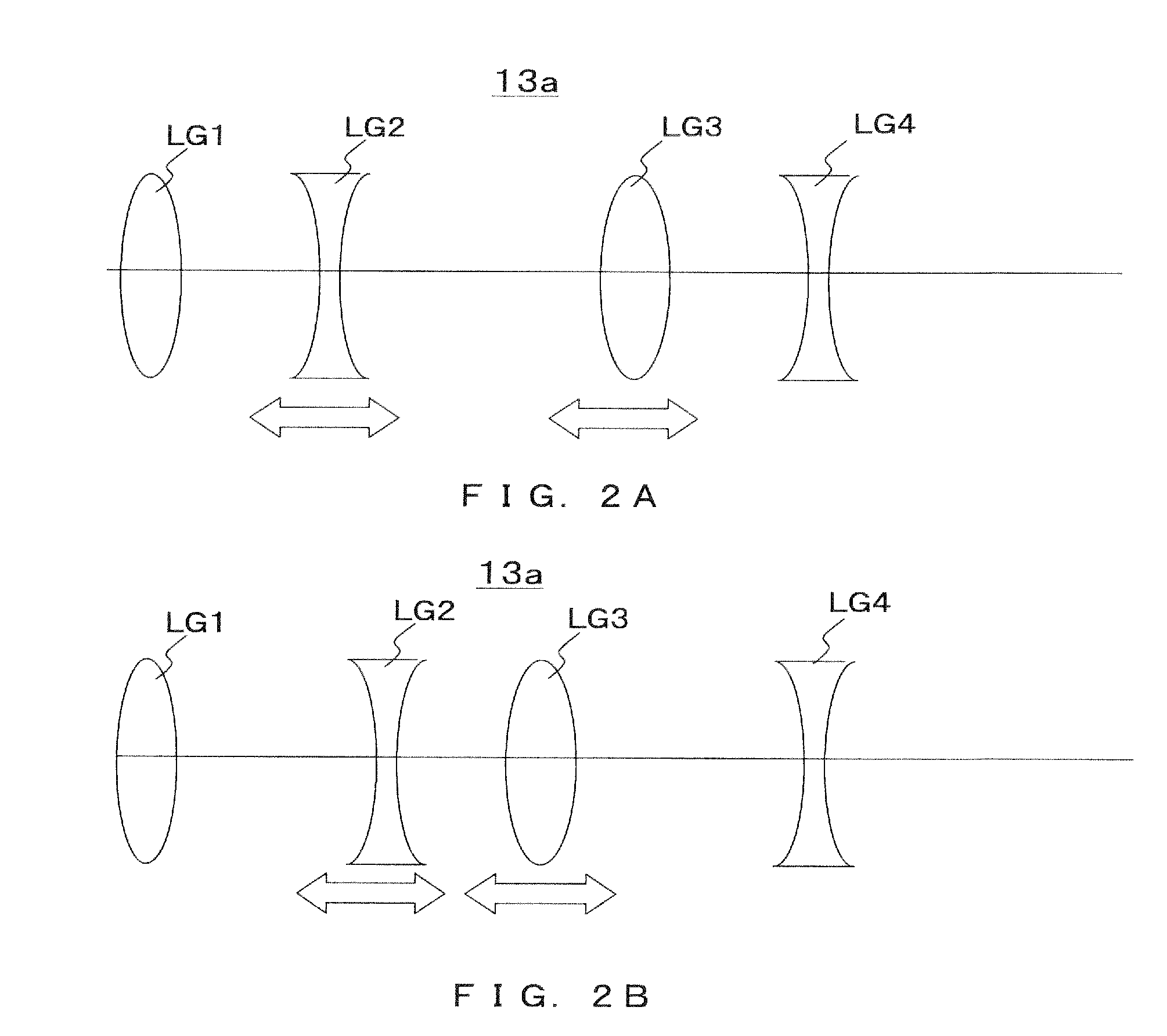
[0048]A laser introduction optical system in the laser scanning microscope of FIG. 4 includes a laser light source 11, a shutter 12, abeam diameter changing optical system 13, a tunable stop 14, a laser light condensing lens 15, a scanning unit 39, a pupil projection lens 40, a tube lens 23, and an objective lens 7, and irradiates the laser light onto the sample. The tunable stop 14 is a field stop in which the diameter of the stop is tunable. Alternatively, the tunable stop 14 may be an insertably and removably configured field stop. In this case, the diameter of the stop can be changed by replacing the field stop with a field stop of a different stop diameter. The beam diameter changing optical system 13 may be configured such that the magnification is tunable by means of the zoom lens. Also, the beam diameter changing optical system 13 itself may be ...
PUM
 Abstract
Description
Claims
Application Information
 - R&D
- Intellectual Property
- Life Sciences
- Materials
- Tech Scout
- Unparalleled Data Quality
- Higher Quality Content
- 60% Fewer Hallucinations
Browse by: Latest US Patents, China's latest patents, Technical Efficacy Thesaurus, Application Domain, Technology Topic, Popular Technical Reports.
© 2025 PatSnap. All rights reserved.Legal|Privacy policy|Modern Slavery Act Transparency Statement|Sitemap|About US| Contact US: help@patsnap.com