
Photovoltaic power farm structure and installation

a photovoltaic power farm and power plant technology, applied in photovoltaic supports, pv power plants, sustainable buildings, etc., can solve the problems of increasing the cost of individual modules, limiting the practical size of individual modules, and high material and manufacturing costs of individual crystalline silicon modules, etc., to achieve the effect of being easily replaced

Inactive Publication Date: 2009-12-03
SOLANNEX
View PDF38 Cites 101 Cited by
  • Summary
  • Abstract
  • Description
  • Claims
  • Application Information

AI Technical Summary

Benefits of technology

[0010]A further object of the invention is to teach methods to reduce cost and complexity of photovoltaic power installations.SUMMARY OF THE INVENTION
[0035]In an embodiment a conducting rail increases in cross section with length to reduce resistive power losses.
[0041]In one embodiment an existing module may be removed simply and readily replaced with a module of improved performance.

Problems solved by technology

The material and manufacturing cost of the individual crystalline silicon modules are relatively high.
In addition, the practical size of the individual module is restricted by weight and batch manufacturing techniques employed.
Installation may often be characterized as “custom designed” for the specific site, which further increases cost.
Because of cost, weight and size restrictions, use of crystalline photovoltaic cells for bulk power generation has developed only slowly in the past.
However, many thin films require heat treatments which are destructive of even the most temperature resistant polymers.
In addition deposition on glass normally forces expensive and delicate material removal processing such as laser scribing to subdivide the expansive surface into individual interconnected cells remaining on the original glass substrate (often referred to as monolithic integration).
Finally, it is difficult to incorporate collector electrodes over the top light incident surface of cells employing glass substrates.
Series interconnecting the large number of resulting individual cells may result in large voltages for a particular module which may be hazardous and require additional expense to insure against electrical shock.
However, because the substrate is conductive, monolithic integration techniques used for nonconductive substrates may be impractical.
However handling, repositioning and integration of the multiple individual cells has proven troublesome.
Such an approach reduces the ultimate value of continuous thin film production by introducing a tedious, expensive batch assembly process.
In addition, such techniques do not produce modular forms conducive to large scale, expansive surface coverage requirements intrinsic in solar farms producing bulk power.
A further issue that has impeded adoption of photovoltaic technology for bulk power collection in the form of solar farms involves installation of multiple modules over expansive regions of surface.
One problem is that the attachment to the cells is normally a manual operation requiring tedious operations such as soldering.
Next, the unwieldy flexible leads must be directed and secured in position outside the boundaries of the module, again a tedious operation.
These are intrinsically tedious manual operations.

Method used


Image

  • Photovoltaic power farm structure and installation
  • Photovoltaic power farm structure and installation
  • Photovoltaic power farm structure and installation

Examples


example 1

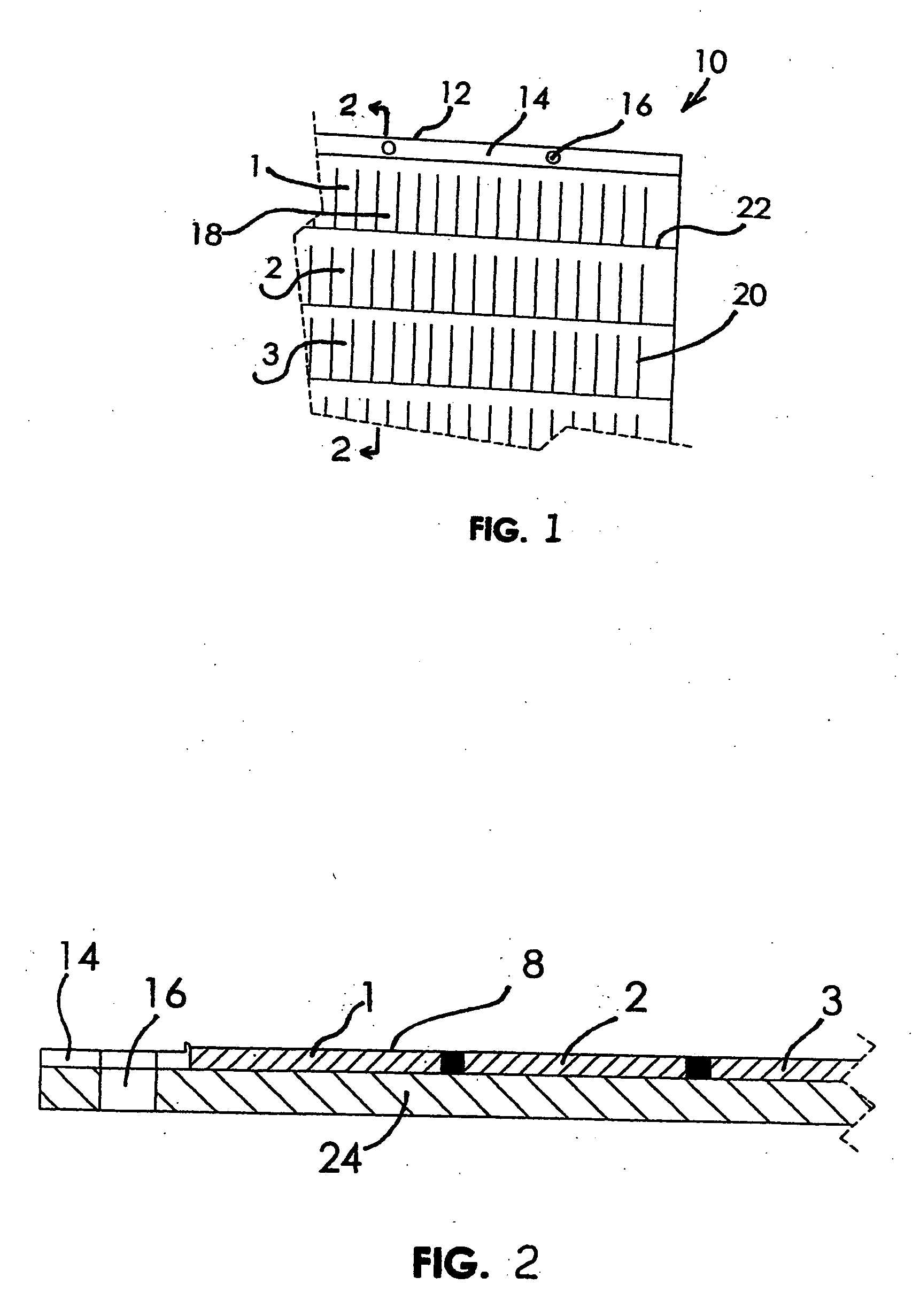
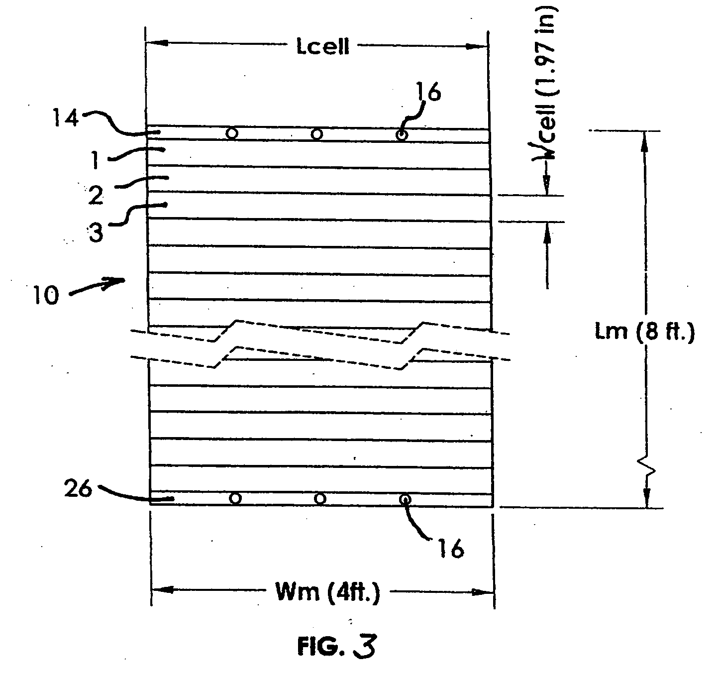
[0095]Modules of multiple interconnected cells comprising thin film CIGS supported by a metal foil are produced. Individual multi-cell modules are constructed according to the teachings of the Luch patent application Ser. No. 11 / 980,010. As noted, other methods of module construction may be chosen. Each individual cell has linear dimension of width 1.97 inches and length 48 inches (4 ft.). 48 of these cells are combined in series extending approximately 94.5 inches in the module length direction perpendicular to the 48 inch length of the cells. Such a modular assembly of cells is expected to produce electrical components of approximately 24 open circuit volts and 15 short circuit amperes. A terminal bar is included to contact the bottom electrode of the cell at one end of the 8 ft. module length. A second terminal bar is included to contact the top electrode of the cell at the opposite end of the 8 ft. length. The terminal bars are readily included according to the teachings of the ...

example 2

[0101]In this example, site preparation is generally similar to that of Example 1 and structures are constructed according to the embodiment of FIG. 16. Modules are manufactured and shipped to the installation site in the form of rolls of extended length. For example, a continuous roll of CIGS cells interconnected in series to form a single module is produced. Individual cells have a width dimension of 1.97 inches and length of 48 inches. The module is 100 ft. in length and has terminal bars at each end of the 100 ft. length. There are 608 series connected cells and the terminal bars are about 1 inch wide and extend across substantially the entire 48 inch width of the module. The modules are accumulated in rolls each of which comprises a 100 ft. module as described.

[0102]The rolls are shipped to the installation site. There, workers position one end at the start of an extended channel such as depicted in FIG. 16. Such a 100 ft. roll of thin film module on a 0.001 inch metal foil sub...


PUM


Abstract

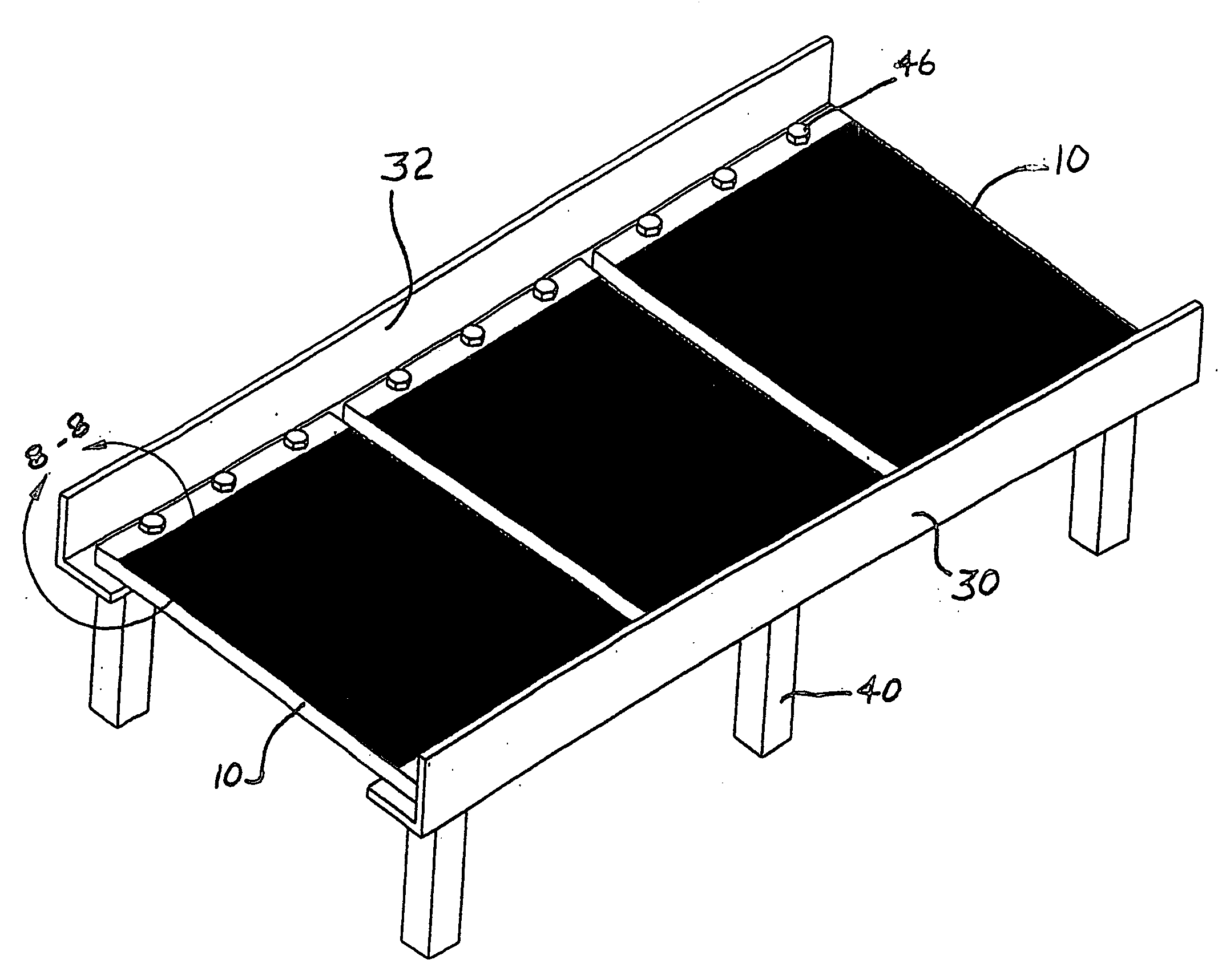
The patent teaches an installation suitable for expansive surface area photovoltaic modules. Installation structure comprises conducting rails functioning as a power conduits to convey power from expansive modules. Multiple modules may be mounted on the installation structure in a parallel or series arrangement. The high current carrying capacity rails minimize power loss in conveyance of power. Module installation and electrical connections are accomplished in a facile fashion using mechanical fasteners to thereby simplify and reduce installation cost associated with production of large photovoltaic generating facilities.

Description

BACKGROUND OF THE INVENTION[0001]Photovoltaic cells have evolved according to two distinct materials and fabrication processes. A first is based on the use of single crystal or polycrystal silicon. The basic cell structure here is defined by the processes available for producing crystalline silicon wafers. The basic form of the wafers is typically a rectangle (such as 6 in.×6 in.) having a thickness of about 0.008 inch. Appropriate doping and heat treating produces individual cells having similar dimensions (6 in.×6 in.). These individual cells are normally subsequently assembled into an array of cells referred to as a module. In the module, series connections are made among the individual cells. A module may typically consist of multiple individual cells connected in series. The series connections may be made by individually connecting a conductor (tab) between the top surface of one cell to the bottom surface of an adjacent cell. In this way multiple cells are connected in a “stri...

Claims


Application Information

Patent Timeline
Patent Type & Authority Applications(United States)
IPC IPC(8): H01L31/048
CPCH01L31/02008H02S20/00Y02E10/50H02S20/23Y02B10/10
Inventor LUCH, DANIEL
Owner SOLANNEX
Learn More