
Electromagnetic wave shielding gasket having elasticity and adhesiveness

a technology of electromagnetic shielding gaskets and elastic materials, applied in the direction of non-metal conductors, conductors, weaving, etc., can solve the problems of reducing the life span of electronic devices or components, deteriorating the image, and reducing the performance of electronic devices, etc., and achieve the effect of simple fabrication

Inactive Publication Date: 2009-11-26
3M INNOVATIVE PROPERTIES CO
View PDF48 Cites 49 Cited by
  • Summary
  • Abstract
  • Description
  • Claims
  • Application Information

AI Technical Summary

Benefits of technology

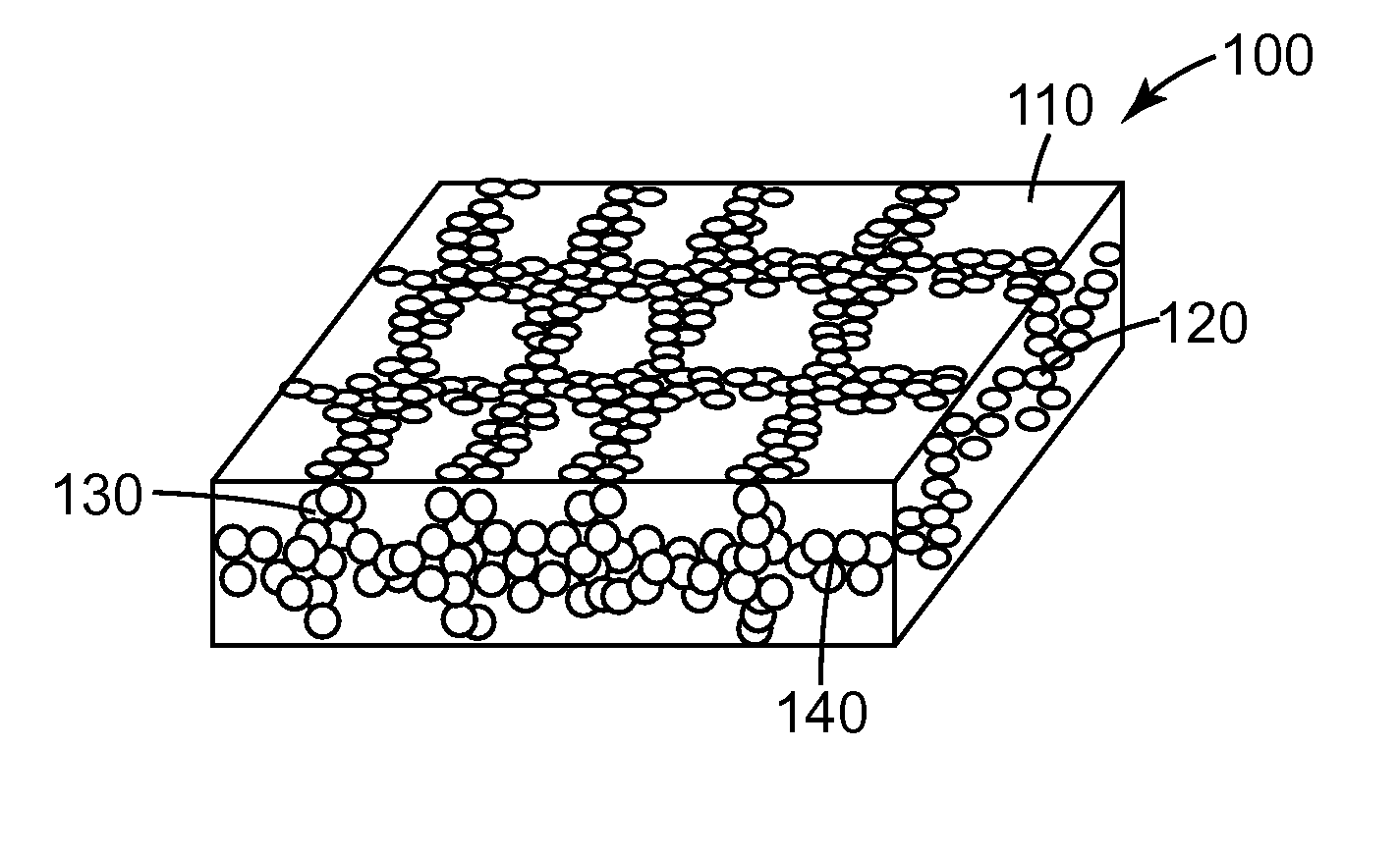
[0015]As a result, inventors of the present invention have developed a method capable of imparting conductivity into adhesive polymer resin in both longitudinal and transverse directions of the adhesive polymer resin. If such adhesive polymer resin is used as a material for a gasket, it is possible to simply obtain an electromagnetic wave shielding gasket having impact and vibration absorbing characteristics with desired surface conductivity and volume conductivity without degrading the properties of the gasket.
[0016]Accordingly, an object of the present invention is to provide an electromagnetic wave shielding gasket, which can be simply fabricated and has impact and vibration absorbing characteristics and the adhesive property with desired surface conductivity and volume conductivity without degrading the property of the gasket.

Problems solved by technology

Various harmful electronic waves or electromagnetic waves generated from circuits of various electronic appliances may cause malfunction of peripheral electronic devices or components thereof, degrade performance of the electronic devices, deteriorate the image while generating noise, reduce the life span of the electronic devices or components thereof, and cause defect to electronic products.
However, in these cases, not only is it difficult to uniformly distribute particles of carbon black, but also melt viscoelasticity of urethane resin is reduced, so that filler particles may cohere with each other, thereby significantly increasing viscosity.
As a result, foaming is impossible and the specific gravity of the product is increased while deteriorating the properties of the product, so that the impact and vibration absorbing property of the product may be degraded.
As mentioned above, the amount of conductive materials must be limited due to the difficulty of the manufacturing process and the property degradation of the product.
For this reason, relatively great volume resistance is presented, so that it is difficult to obtain desired vertical volume conductivity.
As a result, according to the conventional method of mixing conductive filler with polymer resin, it is difficult to obtain the polymeric elastomer, the electromagnetic wave shielding material, or the electromagnetic wave shielding gasket having superior conductivity as well as impact and vibration absorbing properties.
However, this conventional method excessively uses the fillers, so the fabrication cost may increase.
In addition, since the conventional conductive elastomer has no adhesive properties, if a gasket made from the conventional conductive elastomer is applied to the electronic appliance, the gasket may not be easily fixed to the electronic appliance before the product is assembled.
That is, a gasket having impact and vibration absorbing properties and volume conductivity with high elasticity, low hardness and low permanent compression set has not been yet developed.
In addition, a gasket having the self-adhesive property has not been yet developed.

Method used


Image

  • Electromagnetic wave shielding gasket having elasticity and adhesiveness
  • Electromagnetic wave shielding gasket having elasticity and adhesiveness
  • Electromagnetic wave shielding gasket having elasticity and adhesiveness

Examples


embodiment 1

[0115]93 parts of 2-ethyle hexyl acrylate, which is acrylic monomer, 7 parts of acrylic acid, which is polar monomer, and 0.04 parts of Irgacure-651 (α,α-methoxy-α-hydroxyacetophenone), which is photoinitiator, are partially polymerized in a glass reactor having a volume of 1 l, thereby obtaining 3000 cPs syrup. In addition, 100 parts of cPs syrup are mixed with 0.1 part of Irgacure-819 [Bis(2,4,6-trimethylbenzoyl)phenylphosphineoxide], which is photoinitiator, and 0.65 parts of 1,6-hexanediol diacrylate (HDDA), which is cross-linking agent, and the mixture is sufficiently stirred. Then, 30 parts of silver coated hollow glass sphere (SH230S33, Potters Industries Inc.) having a particle size of 44 μm are mixed with the mixture as electroconductive fillers, and then the mixture is sufficiently stirred, thereby obtaining the mixture in the form of polymer syrup.

[0116]Meanwhile, as shown in FIG. 4, the lattice having a width of 700 μm and an interval of 1.5 mm is patterned on a transpar...

embodiment 2

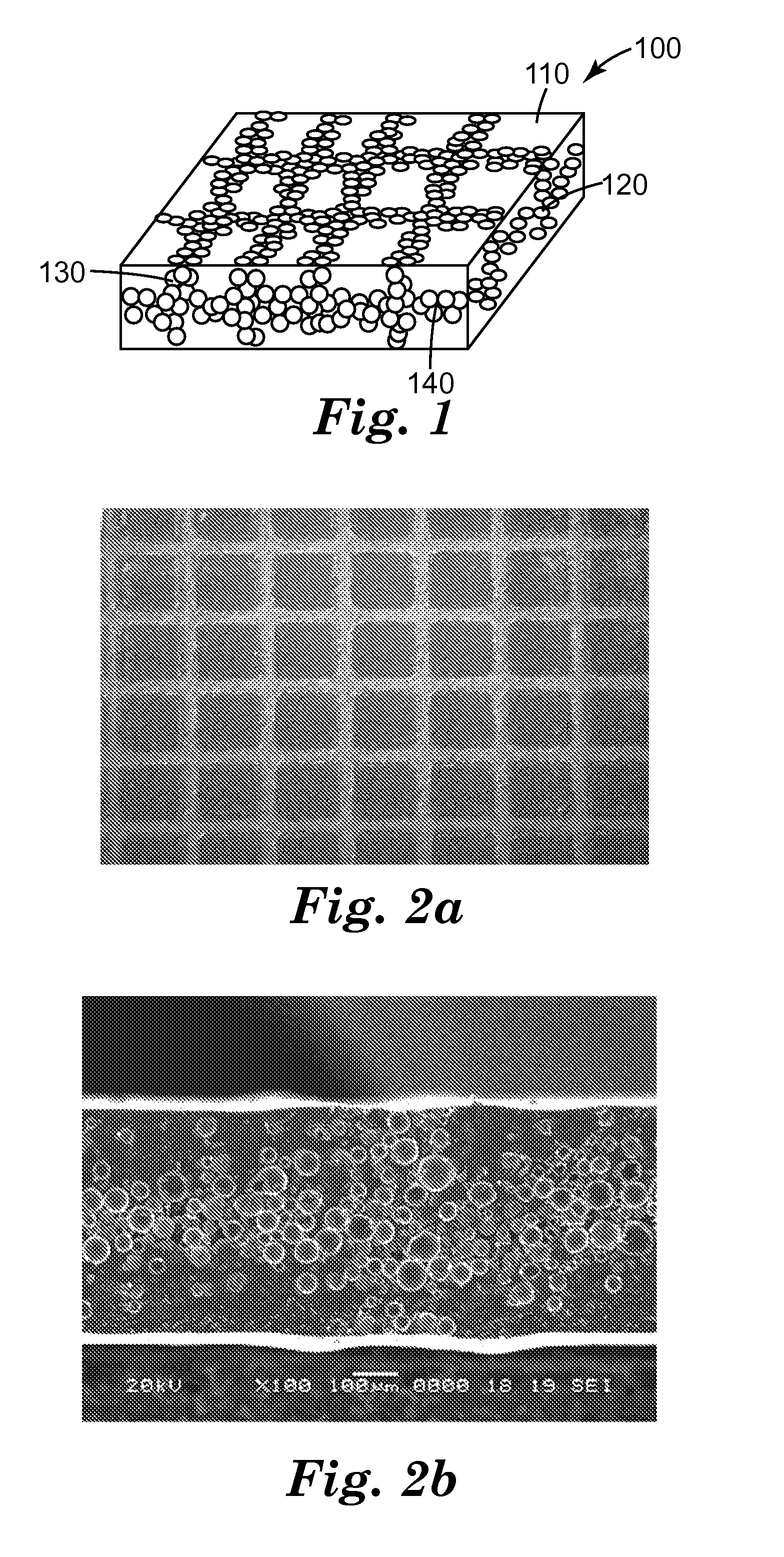
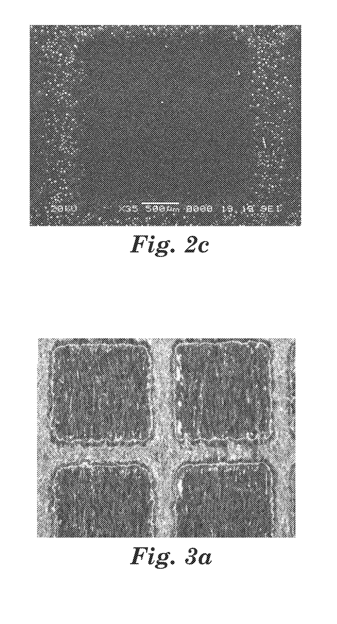
[0120]Embodiment 2 is performed in the same manner as Embodiment 1, except that 60 parts of Ni-coated graphite fiber available from Sulzer Metco Inc. are used as conductive fillers in order to fabricate the gasket. FIGS. 6a to 6c are photographic views taken by an SEM (scanning electron microscope), which show the sectional shape and the upper surface of the adhesive polymer sheet fabricated through Embodiment 2.

embodiment 3

[0121]Embodiment 3 is performed in the same manner as Embodiment 2, except that Ni / Cu coated conductive fabric is used as an electroconductive substrate in order to fabricate the gasket.


PUM

PropertyMeasurementUnit
Fractionaaaaaaaaaa
Percent by massaaaaaaaaaa

Abstract

Disclosed is a gasket having electric and adhesive properties as well as electromagnetic wave shielding functions and a method for manufacturing the same. The gasket includes an adhesive polymer sheet having electrical conductivity and being disposed in the longitudinal and transverse directions of an electroconductive substrate, so that the gasket has impact and vibration absorbing properties in addition to an adhesive property.

Description

BACKGROUND OF THE INVENTION[0001]1. Field of the Invention[0002]The present invention relates to an electromagnetic wave shielding gasket having elastic and adhesive properties and a method for manufacturing the same. More particularly, the present invention relates to an electromagnetic wave shielding gasket, in which an adhesive polymer sheet having electrical conductivity is disposed in the longitudinal and transverse directions of an electroconductive substrate, so that the electromagnetic wave shielding gasket has impact and vibration absorbing properties as well as an adhesive property.[0003]2. Description of the Prior Art[0004]Various harmful electronic waves or electromagnetic waves generated from circuits of various electronic appliances may cause malfunction of peripheral electronic devices or components thereof, degrade performance of the electronic devices, deteriorate the image while generating noise, reduce the life span of the electronic devices or components thereof,...

Claims


Application Information

Patent Timeline
IPC IPC(8): H01B1/12H01B1/22H01B1/24B32B27/12B32B15/08B32B5/16B32B37/00C08F2/48
CPCH05K9/0015H05K9/0096Y10T428/266Y10T428/269Y10T428/25Y10T428/31678Y10T428/249921Y10T442/674H05K9/00
Inventor CHOI, JEONGWANJEONG, HUNKIM, WON-SIK
Owner 3M INNOVATIVE PROPERTIES CO
Learn More