
Temperature sensor

a technology of temperature sensor and connecting wire, which is applied in the direction of liquid/fluent solid measurement, volume/mass flow by thermal effect, instruments, etc., can solve the problem that the conventional compacted powder filler material does not provide sufficient support for the connecting wire, and achieves faster response, increased heat flow, and higher measurement accuracy

Inactive Publication Date: 2009-11-26
EPIQ SENSOR NITE
View PDF16 Cites 11 Cited by
  • Summary
  • Abstract
  • Description
  • Claims
  • Application Information

AI Technical Summary

Benefits of technology

[0008]The gap impedes the heat flow through the filler material and thus provides thermal decoupling between the resistor and the exterior of the exhaust. This improves the level of accuracy achievable by the sensor.
[0010]The housing may be formed from any suitable material including but not limited to stainless steel or nickel base alloys. The housing may have a substantially circular cross-section. The resistor is preferably mounted in a projecting end portion of the housing. The projecting end portion may also be of substantially circular cross-section but is preferably of narrower cross-section than the rest of the housing. By having a narrower cross-section heat flow between the exterior of the projecting portion and the resistor is improved.
[0013]In order to achieve a better heat transfer from the gas to the temperature sensor an additional heat exchange element may be attached to the housing. The additional heat exchange element may be attached to the housing adjacent to the position where the resistor is mounted. The additional heat exchange element may be a plate providing a large contact surface projecting into the exhaust gas. Such a plate will enable increased heat flow form the exhaust gas to the resistor and hence improve the performance of the sensor. The plate may be provided with one or more surface features or ridges adapted to further increase its surface area. The additional heat exchange element may be formed from metal or other material with good heat conductivity.
[0015]The provision of the additional heat exchange element increases the flow of heat from the exhaust gas to the resistor. The increased heat flow from gas to resistor provides a faster response when the exhaust gas temperature rapidly changes and higher measurement accuracy amongst other benefits thus improving the performance of the sensor.

Problems solved by technology

The gap impedes the heat flow through the filler material and thus provides thermal decoupling between the resistor and the exterior of the exhaust.
In contrast, conventional compacted powder filler materials will not provide sufficient support to the connecting wires in the presence of normal mechanical forces such as vibration.

Method used


Image

  • Temperature sensor
  • Temperature sensor

Examples


Embodiment Construction

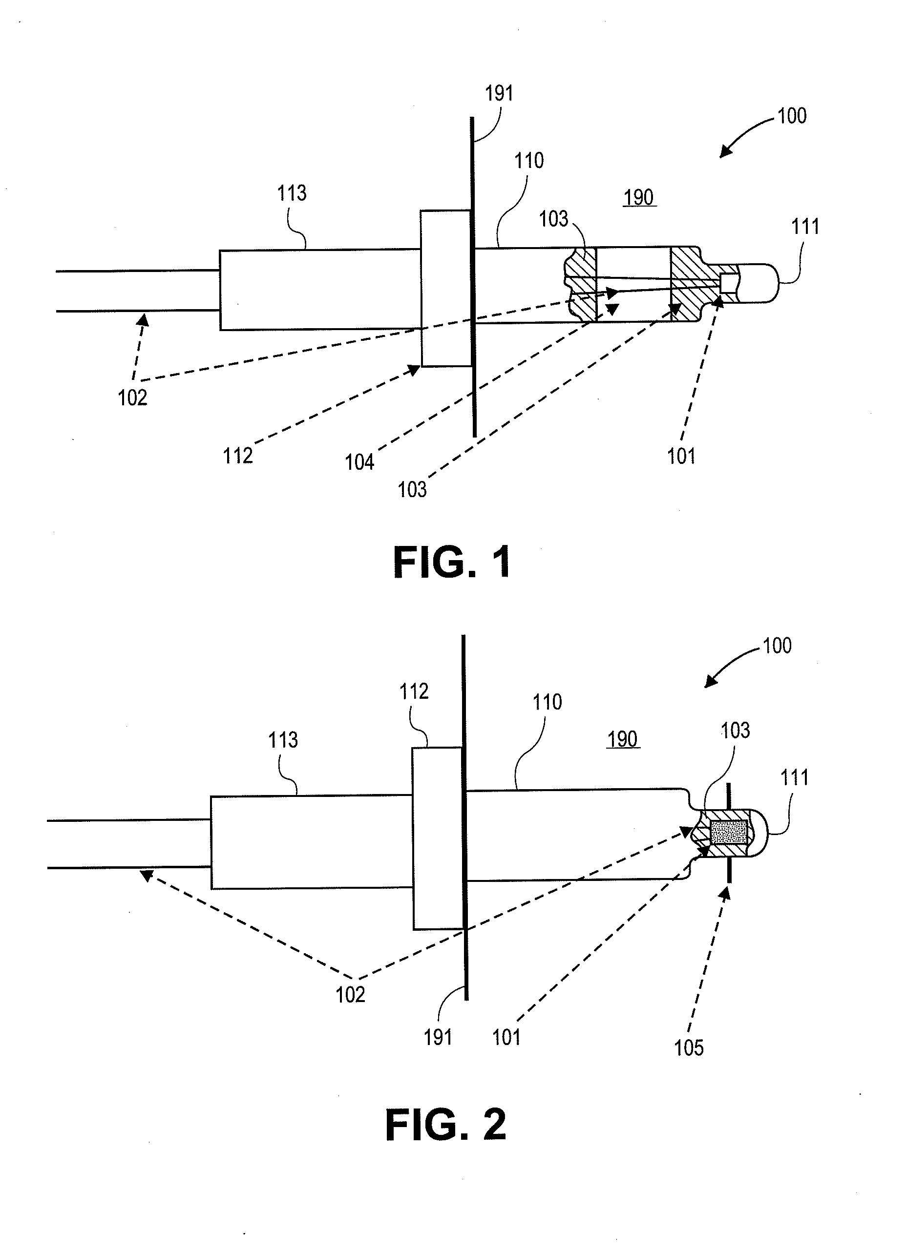
[0021]Referring now to FIG. 1, a temperature sensor 100 projects into an exhaust pipe 190 of a vehicle through a specially provided hole (not shown) in pipe wall 191. The wall 191 divides a hot zone within the pipe 190 from a cold zone exterior to the pipe 190.

[0022]The sensor 100 includes a temperature dependent resistor 101 mounted within a protective housing 110. The housing 110 is formed from materials such as stainless steel, nickel base alloys or similar materials. The resistor 101 is connected to external circuitry via a pair of connecting wires 102. In use, variations in temperature of the exhaust gas cause a variation in the temperature experienced by the resistor 101. Consequently, the resistance of the resistor 101 also varies. The resistance variation can be monitored by external circuitry via the wires 102 so as to provide an indication of the exhaust gas temperature.

[0023]The resistor 101 is mounted in a projecting end portion 111 of the housing which is of narrower cr...


PUM


Abstract

A sensor having a temperature dependent resistor mounted within a protective housing. The resistor is connected to external circuitry via a pair of connecting wires. In use, variations in temperature of the exhaust gas cause a variation in the temperature experienced by the resistor and consequently, the resistance of the resistor also varies. The resistor is mounted in a projecting end portion of the housing which is of narrower cross-section than the bulk of the housing. The housing is filled with a filler material. The filler material provides support to the resistor and the wires. In the present invention, unlike in prior art sensors, the filler material does not completely fill the housing. Instead a gap is provided which is crossed by the wires. The gap interrupts heat flow through the filler material and thus improves the thermal isolation of the resistor and thereby the accuracy of the sensor. In an alternative embodiment, the sensor additionally comprises an additional heat exchange element. The provision of the additional heat exchange element improves the flow of heat from the exhaust gas to the resistor, thus providing a faster response when the temperature rapidly changes and higher measurement accuracy.

Description

CROSS-REFERENCES TO RELATED APPLICATIONS[0001]This application claims priority to UK 0717994.8, filed Sep. 14, 2007, which is hereby incorporated by reference in its entirety for all purposes.BACKGROUND[0002]The present invention relates to a temperature sensor, and in particular to a temperature sensor suitable for monitoring the temperature of gas in a vehicle exhaust system.[0003]In many vehicles the temperature of the exhaust gases is monitored to provide feedback on engine operation. A typical exhaust temperature sensor comprises a temperature dependant resistor element, which is provided within a protective housing. The housing is mounted such that it projects into the exhaust gas flow, with the resistor being mounted at the tip of the housing projecting furthest into the exhaust. An indication of the temperature is obtained by monitoring the resistance of the resistor. This monitoring is facilitated by the provision of a pair of wires running within the housing to connect the...

Claims


Application Information

Patent Timeline
Patent Type & Authority Applications(United States)
IPC IPC(8): G01F1/69
CPCG01K1/08G01K13/02G01K1/18
Inventor URSSENS, JAN-WILLEM BURSSENSVERMEULEN, EWALD
Owner EPIQ SENSOR NITE
Learn More