
Vehicular belt-driven continuously variable transmission and control method thereof

a technology of continuously variable transmission and control method, which is applied in the direction of gearing control, gearing elements, gearing squeezing force, etc., can solve the problems of increasing the cost of continuous variable transmission, so as to achieve simplified structure

Active Publication Date: 2009-11-19
TOYOTA JIDOSHA KK
View PDF11 Cites 3 Cited by
  • Summary
  • Abstract
  • Description
  • Claims
  • Application Information

AI Technical Summary

Benefits of technology

[0009]This invention thus provides a vehicular belt-driven continuously variable transmission that is able to appropriately control belt squeezing force while having a simplified structure realized by eliminating a centrifugal hydraulic pressure canceller chamber on a secondary pulley side.
[0012]Accordingly, although the belt squeezing force would become excessive at maximum speed due to increased thrust generated by centrifugal hydraulic pressure pushing the movable sheave in the direction that increases the belt squeezing force because no centrifugal hydraulic pressure canceller chamber is provided to cancel out that thrust, that belt squeezing force can be inhibited from becoming excessive by reducing the pressure receiving area of the secondary side cylinder. In this case, it is necessary to also reduce the pressure supplied to the secondary side cylinder. Regarding this point, controlling the line pressure and the pressure supplied to the secondary side cylinder independently makes it possible to avoid problems such as the line pressure, together with the pressure supplied to the secondary side cylinder, becoming too low, or not being able to shift to increase the speed due to the hydraulic pressure necessary for the shift not being supplied to the primary side cylinder or the like. Also, when the pressure receiving area of the secondary side cylinder is reduced, the line pressure must be increased to increase the hydraulic pressure supplied to the secondary side cylinder at low running speeds. However, if the line pressure can be controlled independently from the pressure supplied to the secondary side cylinder, an increase in the line pressure can be limited to roughly the speed reduction side (γ>1) so adverse affects on practical fuel consumption can be avoided. Also, the cylinder pressure receiving area of the secondary side cylinder is reduced until the safety factor, with respect to belt slip, of the belt squeezing force obtained when the pressure supplied to the secondary side cylinder is set to the lowest pressure during maximum speed flat road running, in which the vehicle is running at maximum speed on a flat road, becomes a value less than or equal to 1.5, which makes it possible to keep the durability of the belt from declining. As a result, it is possible to provide a vehicular belt-driven continuously variable transmission having a simple structure and enabling the centrifugal hydraulic pressure canceller chamber to be eliminated for all practical purposes.
[0014]Accordingly, the centrifugal hydraulic pressure chamber may be eliminated for all practical purposes, thereby making it possible to provide a vehicular belt-driven continuously variable transmission with a simplified structure.

Problems solved by technology

This centrifugal hydraulic pressure applies thrust to the movable sheave of the secondary pulley in a direction that squeezes the belt such that the belt squeezing force becomes excessive.
Providing this centrifugal hydraulic pressure canceller chamber however makes the continuously variable transmitting portion heavier, less compact, and more expensive.
However, the required structure is rather complex.
Also, the belt squeezing force does not change smoothly as the cylinder pressure receiving area, which is related to the switching of the modes, is switched.

Method used


Image

  • Vehicular belt-driven continuously variable transmission and control method thereof
  • Vehicular belt-driven continuously variable transmission and control method thereof
  • Vehicular belt-driven continuously variable transmission and control method thereof

Examples


Embodiment Construction

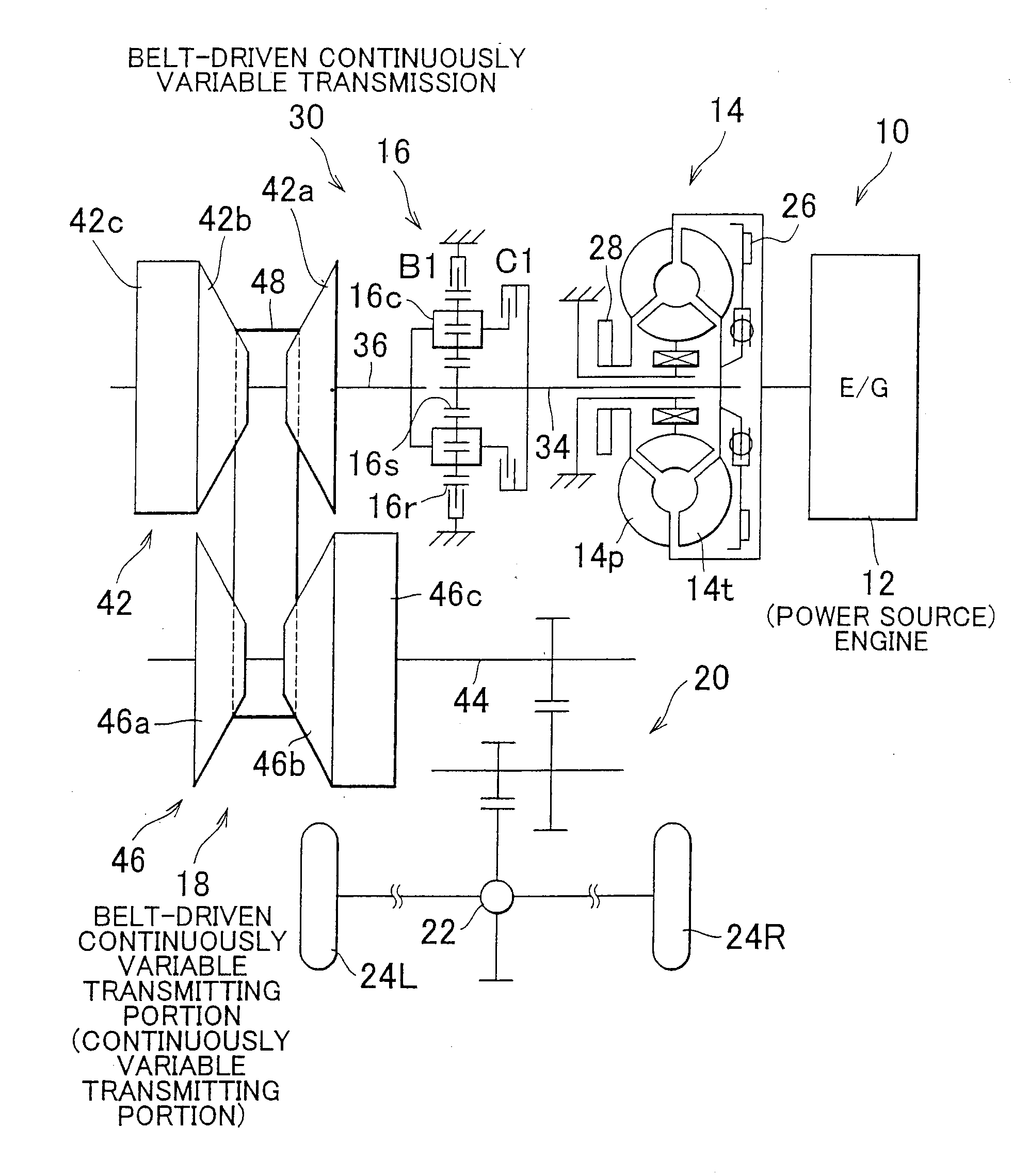
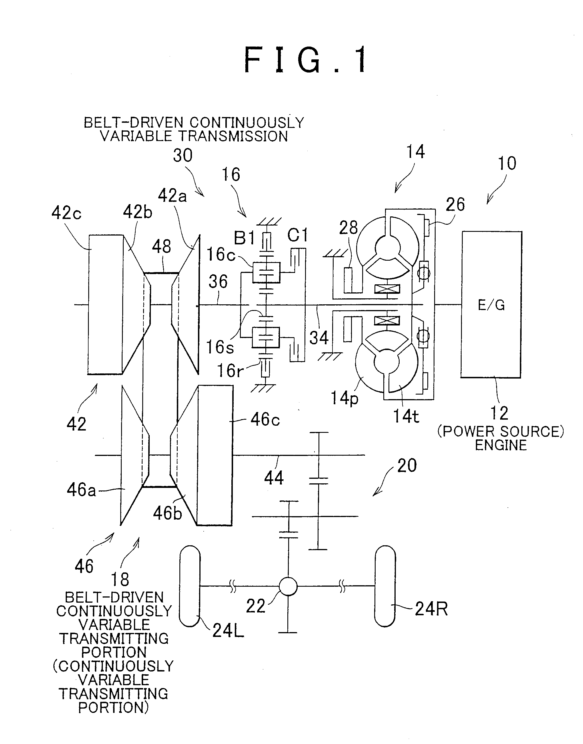
[0023]FIG. 1 is a skeleton view of a vehicular power transmitting device 10 according to one example embodiment of the invention. The vehicular power transmitting device 10 is an automatic transmission for a transverse mounted engine and may be employed in a FF (front engine, front drive) vehicle. The vehicular power transmitting device 10 includes an engine 12 that serves as a power source for running. Output from the engine 12, which is an internal combustion engine, is transmitted from a crankshaft of the engine 12 and a torque converter 14, which is a fluid coupling, to a final reduction gear 22 via a forward-reverse switching apparatus 16, an input shaft 36, a belt-driven continuously variable transmitting portion 18, and a reduction gear device 20, after which it is distributed to left and right driven wheels 24L and 24R. Here the forward-reverse switching apparatus 16 and the belt-driven continuously variable transmitting portion 18 together form a belt-driven continuously va...


PUM


Abstract

In a vehicular belt-driven continuously variable transmission, belt squeezing force is inhibited from becoming excessive and a safety factor, with respect to belt slip, of belt squeezing force applied to a transmission belt (48) is reduced to a value that is less than or equal to 1.5 by reducing a pressure receiving area (SOUT) of an output side hydraulic cylinder (46c). As a result, a centrifugal hydraulic pressure canceller chamber on a secondary pulley side (46) can be eliminated thus simplifying the structure of the vehicular belt-driven continuously variable transmission, while belt squeezing force can be appropriately controlled.

Description

BACKGROUND OF THE INVENTION[0001]1. Field of the Invention[0002]The invention relates to a structure and control method of a vehicular belt-driven continuously variable transmission. More particularly, the invention relates to the structure and control method of a vehicular belt-driven continuously variable transmission that eliminates a centrifugal hydraulic pressure canceller chamber of a secondary side cylinder.[0003]2. Description of the Related Art[0004]One known type of vehicular transmission is a belt-driven continuously variable transmission that shifts speeds smoothly and continuously without any gear switching. This belt-driven continuously variable transmission is formed of a continuously variable transmitting portion that mainly includes two rotating members arranged parallel to one another, a primary pulley provided on one of the rotating members so as not to be able to rotate relative to that rotating member, a secondary pulley provided on the other rotating member so ...

Claims


Application Information

Patent Timeline
Patent Type & Authority Applications(United States)
IPC IPC(8): F16H61/662F16H9/18
CPCF16H2061/66277F16H61/66272F16H9/00F16H61/00F16H61/662
Inventor OGATA, YUSUKESOGA, YOSHINOBUHABUCHI, RYOJIYASUE, HIDEKINAKADA, HIROFUMI
Owner TOYOTA JIDOSHA KK
Learn More