
Method and tooling for dismantling, casking and removal of nuclear reactor core structures

a technology for dismantling, casking and removing nuclear reactor core structures, applied in the field of nuclear reactors, can solve the problems of large cost, large cask thickness, and prior proposals that do not meet these criteria, and achieve the effects of reducing the contact level, increasing the thickness of the cask, and reducing the radiation level of non-activated elements

Active Publication Date: 2009-11-19
WESTINGHOUSE ELECTRIC CORP
View PDF0 Cites 5 Cited by
  • Summary
  • Abstract
  • Description
  • Claims
  • Application Information

AI Technical Summary

Benefits of technology

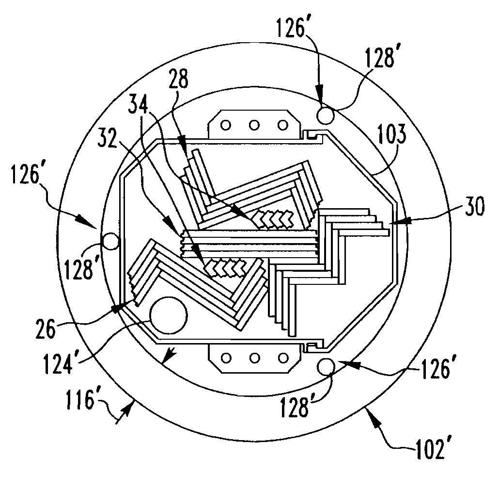
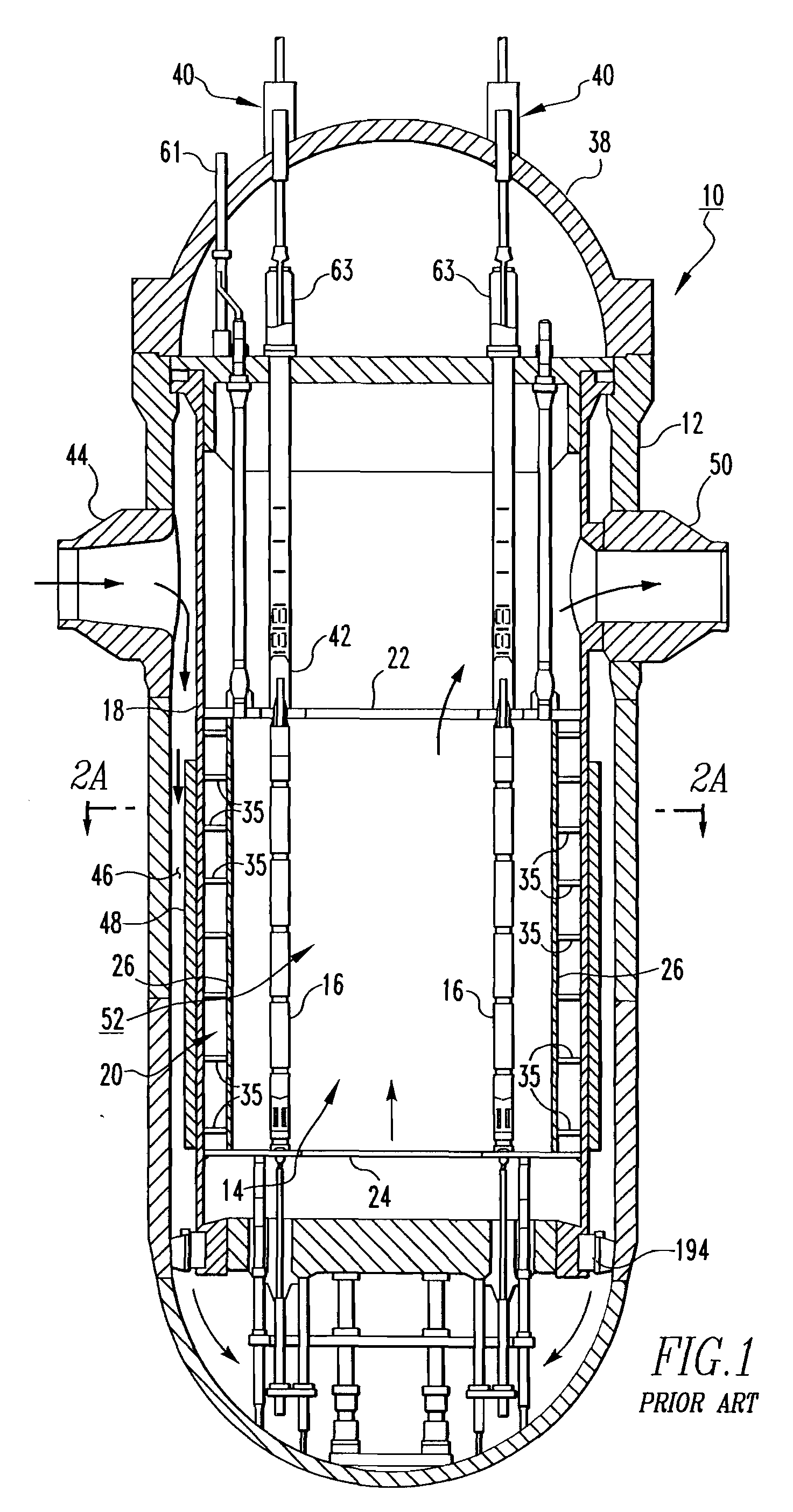
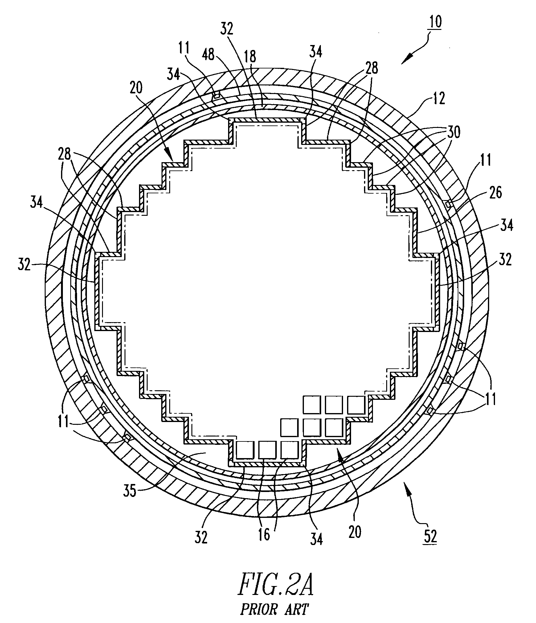
[0014]The method may further comprise draining water from the first cask in the lower internals assembly, and / or positioning indexable guides in die first cask proximate the detached first members. The first cask and the second cask may each have a wall thickness, wherein the wall thickness of the first cask is greater than the wall thickness of the second cask. The wall thickness of the first cask may, for example, be at least twice the wall thickness of the second cask. The first cask and the second cask may also be made from substantially similar materials of construction. In one non-limiting embodiment of the invention, the detached first internals members may have radiation contact levels of at least 500,000 R / hr, and the second cask may have an outside surface with a radiation level of about 800 mR / hr. or less. This level will allow the casked internals to be removed through the equipment hatch of the containment building and transferred to a storage bunker made, for example, from concrete and similar in concept to the bunkers that store casked spent fuel elements on site. The 800 in R / hr. contact level can be markedly reduced, if desired, by adding more shielding, without increasing the cask diameter. Removing the eight irradiation specimen baskets from the thermal shield outside diameter will permit the inside diameter of the lower cask to move radially inward by about 2.7 inches, increasing the cask wall thickness by this amount. As will be discussed herein below, the upper cask can also increase shielding, again without increasing cask envelope diameter, if necessitated by the radiation levels on the upper core plate element in the upper internals. Additionally, the upper support plate of the upper internals can be vacuumed to remove radioactive crud and aggressive chemical decamination remains as another means of reducing radiation levels of non-activated elements of the internals.

Problems solved by technology

Unfortunately, prior proposals do not satisfy these criteria.
The building must then be restored after the task is completed, at great expense.
This generally results in the cask(s) having relatively thick walls, thus being large and heavy.
Such a large cask severely limits the number of manufacturing vendors who have the necessary equipment to cast, machine and handle thick walled cylinders of the magnitude necessary.
Additional disadvantages included extended material procurement and manufacturing schedules.
Accordingly, such a process is cost-intensive.

Method used


Image

  • Method and tooling for dismantling, casking and removal of nuclear reactor core structures
  • Method and tooling for dismantling, casking and removal of nuclear reactor core structures
  • Method and tooling for dismantling, casking and removal of nuclear reactor core structures

Examples


example method

[0077]A non-limiting EXAMPLE of an operation employing the method of the invention will now be discussed. Specifically, FIG. 9A shows the lower internals 52 residing in its storage stand 8 after the core barrel 18 has been removed from the pressure vessel 12. A number of head and vessel alignment pins 193 are provided at the mating surface. At an elevation of about 290 inches above the reactor cavity floor 3, the core barrel 18 is parted using a plasma torch 140 (shown in simplified form) mounted, for example, on a track assembly 142 such as, for example and without limitation, a BUGO TRACK®, which is affixed by clamps or suction cups to either the core barrel 18 or thermal shield outer diameter. A BUGO TRACK® is commercially available from BUG-O Systems, Inc. which has a place of business in Pittsburgh. Pa. The torch 140 will track around the circumference of the core barrel 18 (a distance of about 430 inches), thereby severing the upper section 60. Depending on each specific plant...


PUM


Abstract

A method is provided for removing radioactive internals structural members in the core of a reactor pressure vessel in a containment vessel. The method includes placing a first cask in a first internals assembly, detaching radioactive first internals structural members from second internals structural members of the first internals assembly, placing the detached first internals structural members in the first cask, placing the first internals assembly in a second cask, and removing the second cask containing the first internals assembly and containing the casked detached radioactive first internals members from the containment vessel. The first internal members may be radioactive baffle plates, and the second internals members may be former plates bolted to the radioactive baffle plates. Novel tooling, framework and fixtures facilitate disassembling, moving and storing the radioactive baffle plates.

Description

CROSS-REFERENCE TO RELATED APPLICATION[0001]This application claims the priority of Provisional Application Serial No. 60 / 762,392, filed Jan. 26, 2006, entitled “PROCESS AND UNIQUE TOOLING FOR DISMANTLING, CASKING AND REMOVAL OF NUCLEAR REACTOR CORE.”BACKGROUND OF THE INVENTION[0002]1. Field of the Invention[0003]The invention relates generally to nuclear reactors and, more particularly, to methods and tooling for dismantling, casking and removing nuclear reactor core structures from the containment building, for example, for on-site storage or transport off-site for disposal.[0004]2. Background Information[0005]As nuclear reactors age, utility companies desire to extend plant life. There is also a desire for design upgrades in some circumstances. Accordingly, the replacement of reactor internals (e.g. core structures) is coming into prominence.[0006]To remove and replace radioactive structural members of the reactor internals efficiently and cost-effectively, a number of factors mu...

Claims


Application Information

Patent Timeline
IPC IPC(8): G21C19/00
CPCG21C19/20G21C19/32Y02E30/40G21D1/003G21C19/34Y02E30/00Y02E30/30Y02W30/50
Inventor BALOG, LEONARD J.HACKLEY, THOMAS A.KRAMER, ARTHUR W.
Owner WESTINGHOUSE ELECTRIC CORP
Learn More