
Hollow fiber, dope composition for forming hollow fiber, and method of preparing hollow fiber using the same

a technology of hollow fiber and dope solution, which is applied in the field of hollow fiber, can solve the problems of limited number of gas separation methods, difficult to obtain separation and permeation capabilities beyond a predetermined upperbound, and relatively short history of gas separation using the membrane process. , to achieve the effect of excellent gas permeability, good endurance, and good mechanical strength and chemical stability

Active Publication Date: 2009-11-19
IUCF HYU (IND UNIV COOP FOUNDATION HANYANG UNIV)
View PDF43 Cites 14 Cited by
  • Summary
  • Abstract
  • Description
  • Claims
  • Application Information

AI Technical Summary

Benefits of technology

[0080]The hollow fiber has excellent gas permeability, selectivity, mechanical strength, and chemical stability, and good endurance to stringent condition such as long operation time, acidic conditions, and high humidity.

Problems solved by technology

On the other hand, gas separation using the membrane process has a relatively short history.
However, polymeric materials having membrane performance available commercially for use in gas separation (in the case of air separation, oxygen permeability is 1 Barrer or higher, and oxygen / nitrogen selectivity is 6.0 or higher) are limited to only a few types.
This is because there is considerable limitation in improving polymeric structures, and great compatibility between permeability and selectivity makes it difficult to obtain separation and permeation capabilities beyond a predetermined upperbound.
Furthermore, conventional polymeric membrane materials have a limitation of permeation and separation properties and disadvantages in that they undergo decomposition and aging upon a long-term exposure to high pressure and high temperature processes or to gas mixtures containing hydrocarbon, aromatic and polar solvents, thus causing a considerable decrease in inherent membrane performance.
Due to these problems, in spite of their high economic value, gas separation processes are utilized in considerably limited applications to date.

Method used


Image

  • Hollow fiber, dope composition for forming hollow fiber, and method of preparing hollow fiber using the same
  • Hollow fiber, dope composition for forming hollow fiber, and method of preparing hollow fiber using the same
  • Hollow fiber, dope composition for forming hollow fiber, and method of preparing hollow fiber using the same

Examples


example 1

[0198]A hollow fiber including polybenzoxazole represented by Chemical Formula 51 was prepared using the polyhydroxyamic acid-containing dope solution composition for forming a hollow fiber through the following Reaction Scheme 3.

[0199](1) Preparation of Polyhydroxyamic Acid

[0200]36.6 g (0.1 mol) of 2,2-bis(3-amino-4-hydroxyphenyl) hexafluoropropane and 44.4 g (0.1 mol) of 4,4′-(hexafluoroisoproylidene)diphthalic anhydride was added into 189 g (70 wt %) of N-methylpyrrolidone (NMP) and then reacted at 15° C. for 4 hours to obtain a pale yellow Viscous polyamic acid.

[0201](2) Preparation of a Dope Solution Composition for Forming a Hollow Fiber

[0202]The resulting polyamic acid was added to 5 wt % of tetrahydrofuran as an additive without removal of the solvent to prepare a homogeneous dope solution composition for forming a hollow fiber.

[0203](3) Preparation of Hollow Fiber

[0204]The dope solution composition for forming a hollow fiber was defoamed at ambient temperature under reduced...

example 2

[0206]A hollow fiber including polybenzothiazole represented by Chemical Formula 52 was prepared using the polythioamic acid-containing dope solution composition for forming a hollow fiber through the following reaction.

[0207]A hollow fiber including polybenzothiazole represented by the above Chemical Formula 52 was prepared in the same manner as in Example 1, except that for starting materials, 20.8 g (0.1 mol) of 2,5-diamino-1,4-benzenedithiol dihydrochloride and 44.4 g (0.1 mol) of 4,4′-(hexafluoroisoproylidene)diphthalic anhydride were reacted to prepare polyamic acid including a thiol group (—SH).

[0208]The hollow fiber thus prepared had a weight average molecular weight of 14,500. As a result of FT-IR analysis, characteristic bands of polybenzothiazole at 1484 cm−1(C—S) and 1404 cm−1(C—S) which were not detected in polyimide. The hollow fiber has a fractional free volume of 0.26, and interplanar distance (d-spacing) of 610 pm. The interplanar distance (d-spacing) was measured b...

example 3

[0209]A hollow fiber including polypyrrolone represented by Chemical Formula 53 was prepared using the polyaminoamic acid-containing dope solution composition for forming a hollow fiber through the following reaction.

[0210]A hollow fiber including polypyrrolone represented by the above Chemical Formula 53 was prepared in the same manner as in Example 1, except that for starting materials, 21.4 g (0.1 mol) of 3,3′-diaminobenzidine and 44.4 g (0.1 mol) of 4,4′-(hexafluoroisoproylidene)diphthalic anhydride were reacted to prepare polyamic acid including an amine group (—NH2).

[0211]The hollow fiber thus prepared had a weight average molecular weight of 18,000. As a result of FT-IR analysis, characteristic bands of polypyrrolone at 1758 cm−1(C═O) and 1625 cm−1(C═N) which were not detected in polyimide. The hollow fiber has a fractional free volume of 0.28, and interplanar distance (d-spacing) of 630 pm. The interplanar distance (d-spacing) was measured by X-ray diffraction (XRD, CuKα ray...


PUM

PropertyMeasurementUnit
interplanar distanceaaaaaaaaaa
FWHMaaaaaaaaaa
viscosityaaaaaaaaaa

Abstract

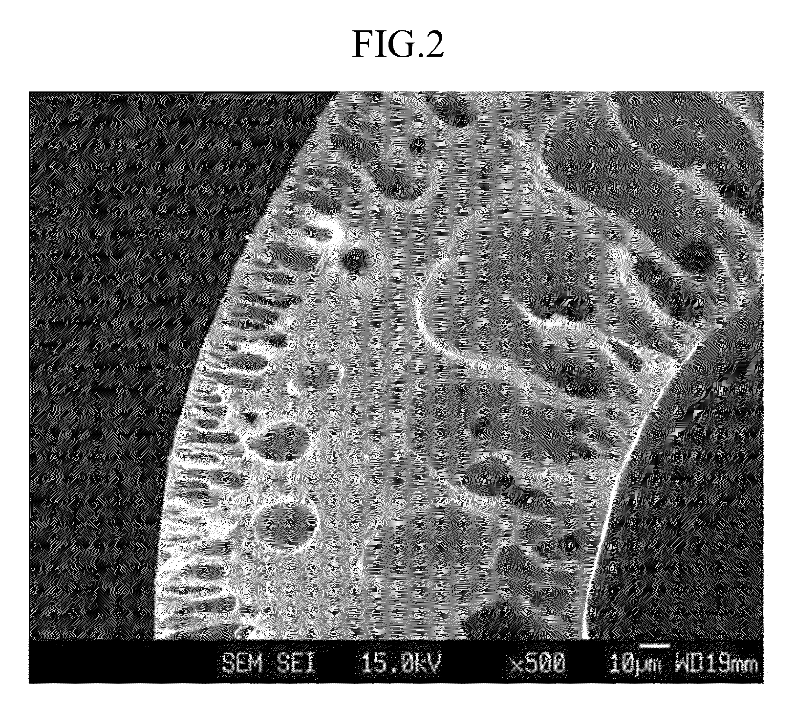
Disclosed is a hollow fiber that includes a hollow positioned at the center of the hollow fiber, macropores positioned at adjacent to the hollow, and mesopores and picopores positioned at adjacent to macropores, and the picopores are three dimensionally connected to each other to form a three dimensional network structure. The hollow fiber includes a polymer derived from polyamic acid, and the polyamic acid includes a repeating unit obtained from aromatic diamine including at least one ortho-positioned functional group with respect to an amine group and dianhydride.

Description

CROSS-REFERENCE TO RELATED APPLICATION[0001]This application claims priority to and the benefit of Korean Patent Application No. 10-2008-0046115 filed in the Korean Intellectual Property Office on May 19, 2009, the entire contents of which are incorporated herein by reference.BACKGROUND OF THE INVENTION[0002](a) Field of the Invention[0003]This disclosure relates to a hollow fiber, a dope solution composition for forming a hollow fiber, and a method of preparing a hollow fiber using the same.[0004](b) Description of the Related Art[0005]Membranes must satisfy the requirements of superior thermal, chemical and mechanical stability, high permeability and high selectivity so that they can be commercialized and then applied to a variety of industries. The term “permeability” used herein is defined as a rate at which a substance permeates through a membrane. The term “selectivity” used herein is defined as a permeation ratio between two different gas components.[0006]Based on the separat...

Claims


Application Information

Patent Timeline
Patent Type & Authority Applications(United States)
IPC IPC(8): B01D69/08D01D5/24B01D67/00B01D71/82B01D53/22C08K5/1535C08K5/3415C08K5/05
CPCB01D69/08B01D69/087B01D71/64C08G73/1039C08G73/1042C08G73/1046C08G73/105C08G73/1053C08G73/1067C08G73/1071C08G73/22C08G75/32C08L79/04C08L79/08C08L81/00C08L2205/05D01D5/06D01D5/24D01D10/02D01F6/74B01D53/22B01D63/021B01D2256/12B01D2256/16B01D2256/18B01D2256/22B01D2257/102B01D2257/702B01D2325/02Y02C20/20Y10T428/2938Y10T428/2969Y10T428/2975C08L79/02B01D71/00
Inventor JUNG, CHUL-HOHAN, SANG-HOONLEE, YOUNG-MOOPARK, HO-BUM
Owner IUCF HYU (IND UNIV COOP FOUNDATION HANYANG UNIV)
Learn More