Immersion system, exposure apparatus, exposing method, and device fabricating method

a technology of exposure apparatus and exposing method, which is applied in the direction of printers, instruments, photosensitive materials, etc., can solve the problems of failure to satisfactorily and continuously fill the optical path with liquid, defects in the pattern formed in the substrate, and failure to prevent failure to expos

Active Publication Date: 2009-11-12
NIKON CORP
View PDF24 Cites 25 Cited by
  • Summary
  • Abstract
  • Description
  • Claims
  • Application Information

AI Technical Summary

Benefits of technology

[0014]According to some aspects of the present invention, an optical path of exposure light can be satisfactorily filled with a liquid and thereby prevent exposure failures from occurring and defective devices from being produced.

Problems solved by technology

If the optical path cannot be satisfactorily filled with the liquid, for example, if a gas portion, such as a bubble, occurs in the liquid, then exposure failures may occur; for example, defects may occur in the pattern formed in the substrate.
In addition, if the substrate is moved at high speed in the state wherein the optical path between the substrate and, for example, the optical member is filled with the liquid, then it becomes difficult to satisfactorily and continuously fill the optical path with the liquid, and the liquid may leak out from a prescribed space, remain on the substrate, or the like.
Furthermore, the heat of vaporization of the leaked or residual liquid may induce changes in the temperature of the optical path, thermal deformation in the various members, such as the substrate, or the like.
In this case, too, exposure failures may occur.
As a result, defective devices could be produced.

Method used


Image

  • Immersion system, exposure apparatus, exposing method, and device fabricating method
  • Immersion system, exposure apparatus, exposing method, and device fabricating method
  • Immersion system, exposure apparatus, exposing method, and device fabricating method

Examples


Embodiment Construction

[0026]The following text explains the embodiments of the present invention referencing the drawings, but the present invention is not limited thereto. The explanation below defines an XYZ orthogonal coordinate system, and the positional relationships among members are explained referencing this system. Prescribed directions within the horizontal plane are the X axial directions, directions orthogonal to the X axial directions in the horizontal plane are the Y axial directions, and directions orthogonal to the X axial directions and the Y axial directions (i.e., the vertical directions) are the Z axial directions. In addition, the rotational (inclination) directions around the X, Y, and Z axes are the θX, θY, and θZ directions, respectively.

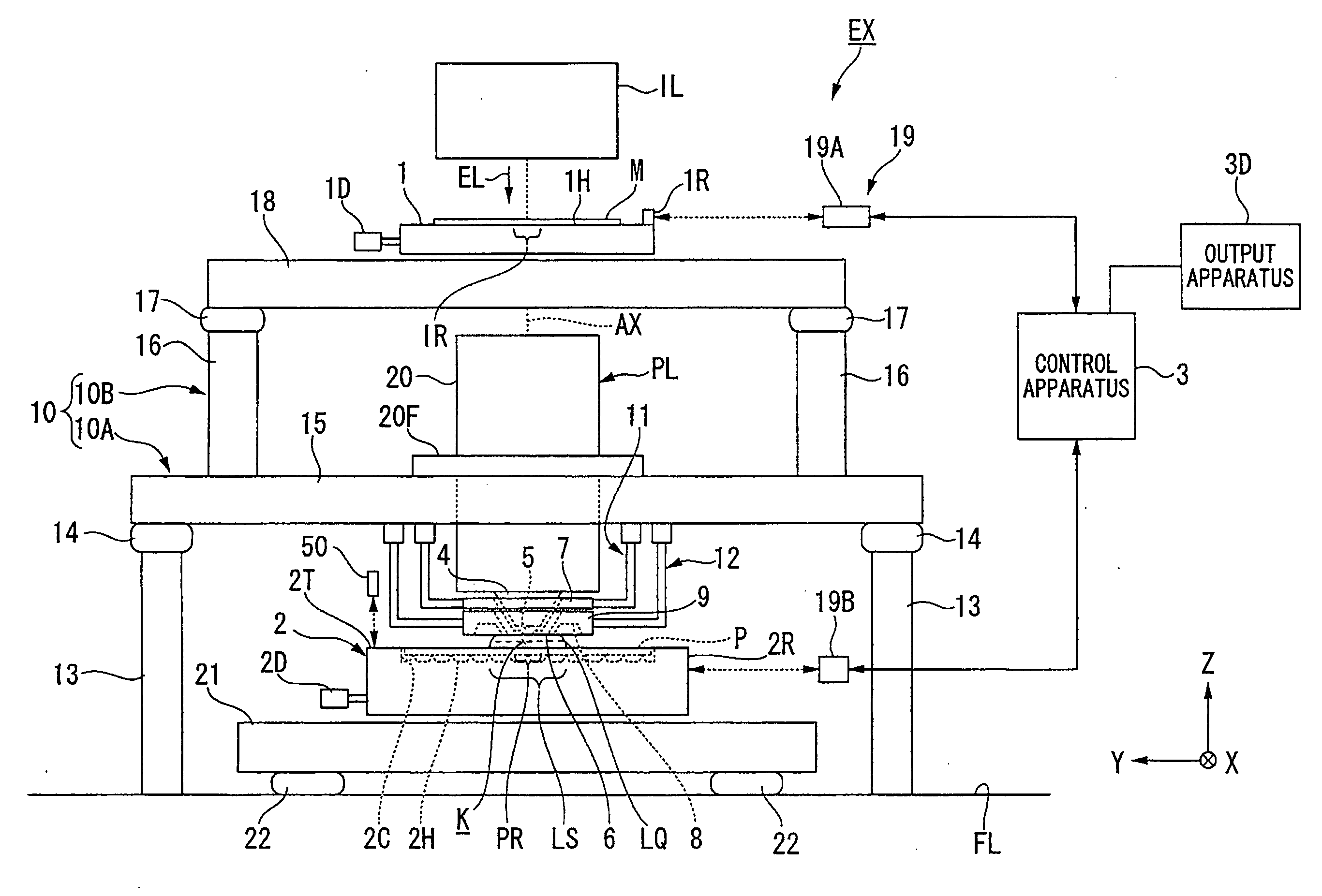
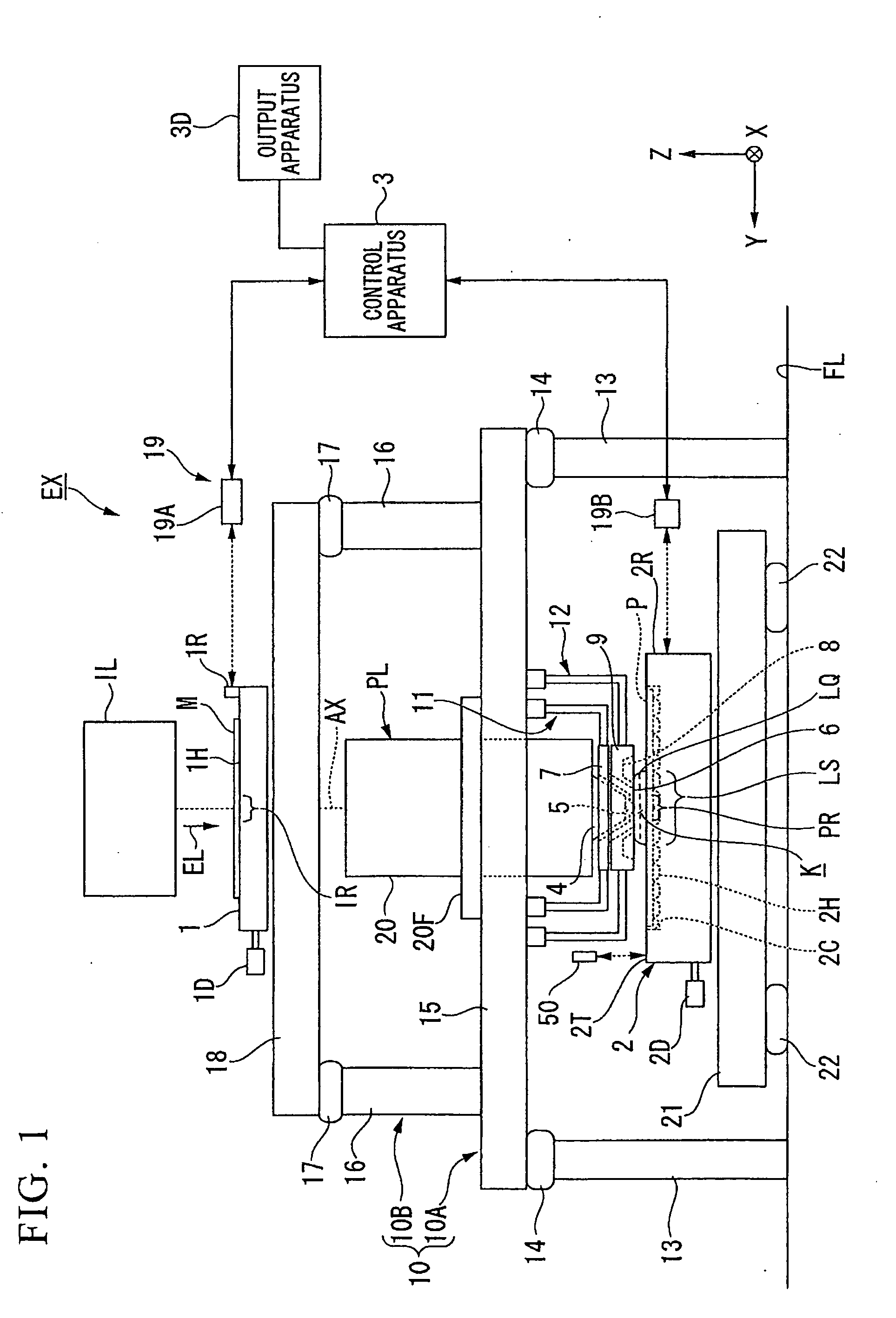
[0027]FIG. 1 is a schematic block diagram that shows one example of an exposure apparatus EX according to the present embodiment. In FIG. 1, the exposure apparatus EX comprises: a movable mask stage 1, which holds a mask M; a movable substrate sta...


PUM

PropertyMeasurementUnit
wavelengthaaaaaaaaaa

Abstract

An immersion system is used in an immersion exposure, wherein a substrate is exposed with an exposure light through an optical member and a liquid, and that fills an optical path of the exposure light between the optical member and the substrate with the liquid. The immersion system comprises: a first member, which is disposed around the optical path of the exposure light and has a first surface that faces in a first direction; a second member that has a liquid recovery port, which is disposed on the outer side of the first surface with respect to the optical path of the exposure light; a first drive apparatus that is capable of moving the first member parallel to the first direction; and a second drive apparatus that is capable of moving the second member parallel to the first direction independently of the first member; wherein, a space between the first surface and a front surface of an object can hold the liquid; and a liquid between the liquid recovery port and the front surface of the object is recovered via the liquid recovery port.

Description

CROSS-REFERENCE TO RELATED APPLICATION[0001]This application is a non-provisional application claiming priority to and the benefit of U.S. provisional application No. 61 / 064,810, filed Mar. 27, 2008. The entire contents of which are incorporated herein by reference.BACKGROUND[0002]1. Field of the Invention[0003]The present invention relates to an immersion system, an exposure apparatus, an exposing method, and a device fabricating method.[0004]2. Description of Related Art[0005]As disclosed in U.S. Patent Application Publication No. 2006 / 0250593 and U.S. Patent Application Publication No. 2007 / 0296939, among exposure apparatuses used in photolithography, an immersion exposure apparatus is known that exposes a substrate with exposure light through a liquid.[0006]In an immersion exposure apparatus, it is critical to satisfactorily fill the optical path of the exposure light between the substrate and an optical member, such as a projection optical system, with the liquid. If the optica...

Claims


Application Information

Patent Timeline
Patent Type & Authority Applications(United States)
IPC IPC(8): G03F7/20G03D3/00
CPCG03F7/70341G03F7/2041H01L21/0274H01L21/0275
Inventor NISHII, YASUFUMI
Owner NIKON CORP
Why Eureka
Try Eureka