Electromagnetic Method on Shallow Water Using a Controlled Source

Inactive Publication Date: 2009-11-12
MULTIFIELD GEOPHYSICS
View PDF7 Cites 9 Cited by
  • Summary
  • Abstract
  • Description
  • Claims
  • Application Information

AI Technical Summary

Benefits of technology

[0015]The present invention provides a solution to some of the above problems, and is a method for analysing acquired electromagnetic measurements R made on or in a sea 4 over a seafloor 1 with rock formations 3 having relatively low resistivity ρ3 for detecting a possibly underlying petroleum bearing reservoir formation 2 having relatively high resistivity ρ2, In which a low frequency electromagnetic transmitter 5 is arranged in the sea 4 and emits an electromagnetic field P propagating in the sea 4, in the rocks 3, 2 and in the air 0 above the sea; in which electromagnetic sensors 6 are arranged with desired offsets x in the sea 4 for measuring the electromagnetic field P(x) while the field propagates, c

Problems solved by technology

However, the field gradients may be considerable in the near fie

Method used


Image

  • Electromagnetic Method on Shallow Water Using a Controlled Source
  • Electromagnetic Method on Shallow Water Using a Controlled Source
  • Electromagnetic Method on Shallow Water Using a Controlled Source

Examples


Example

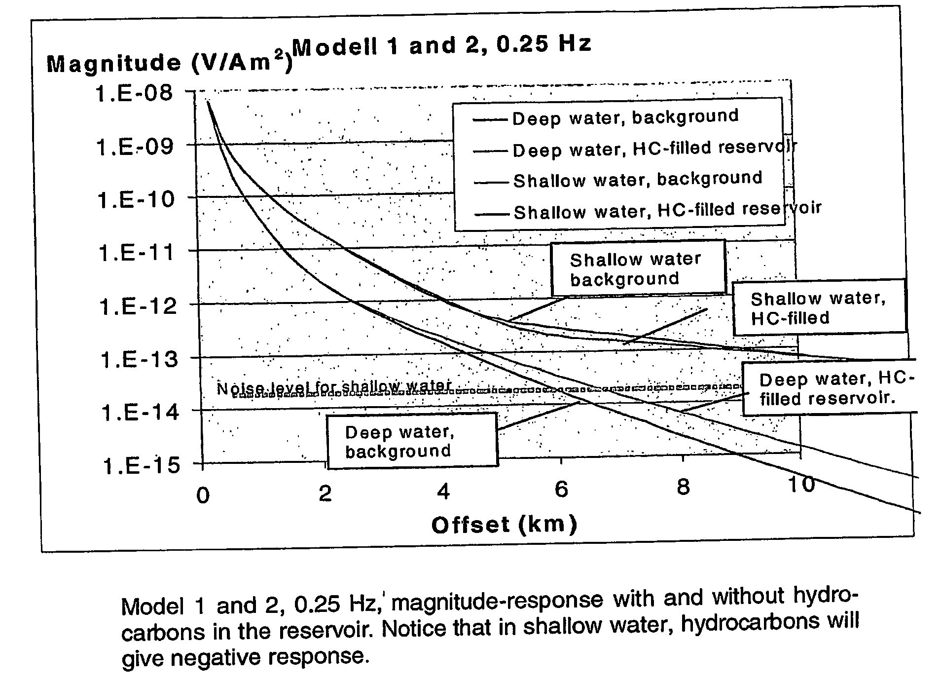
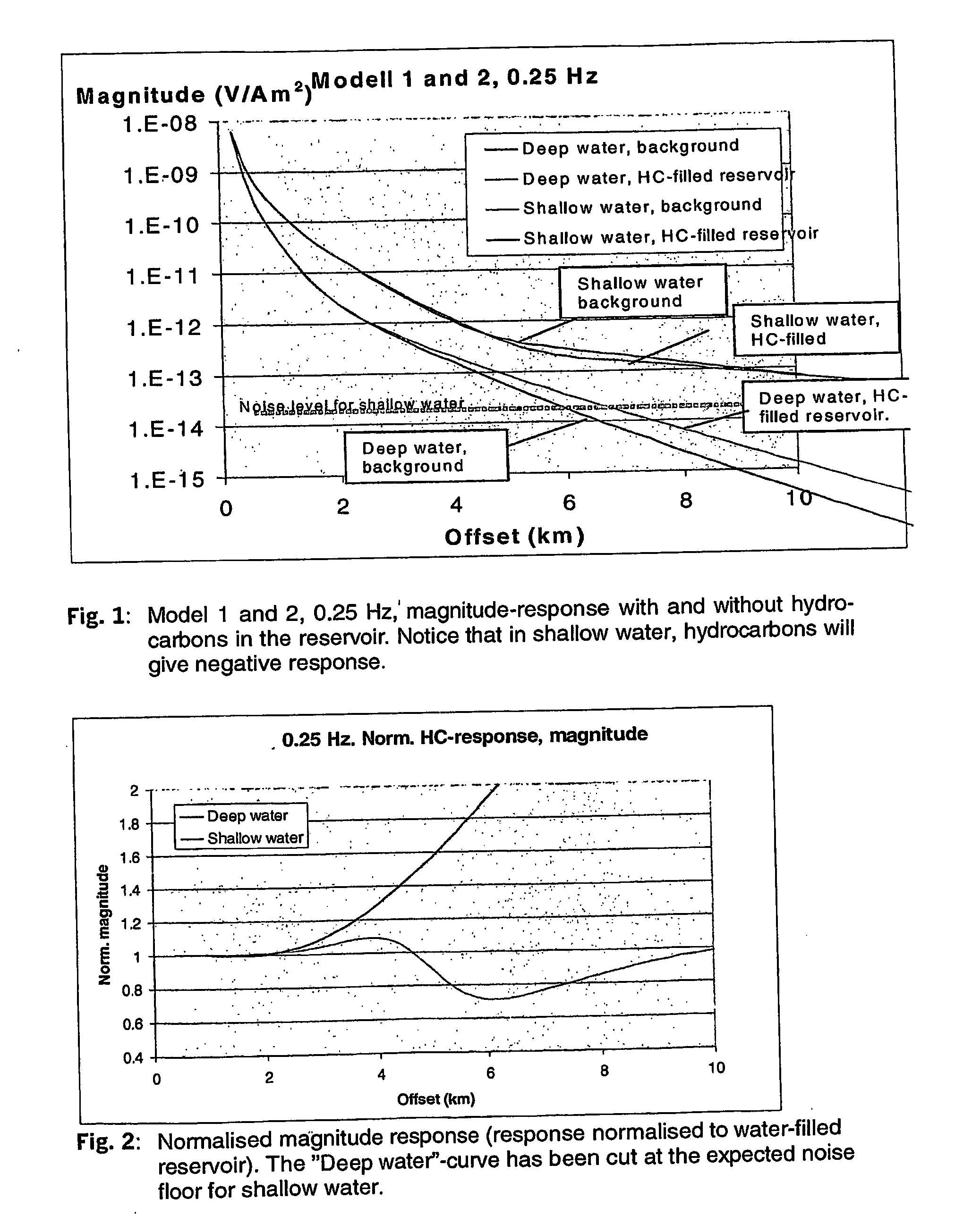
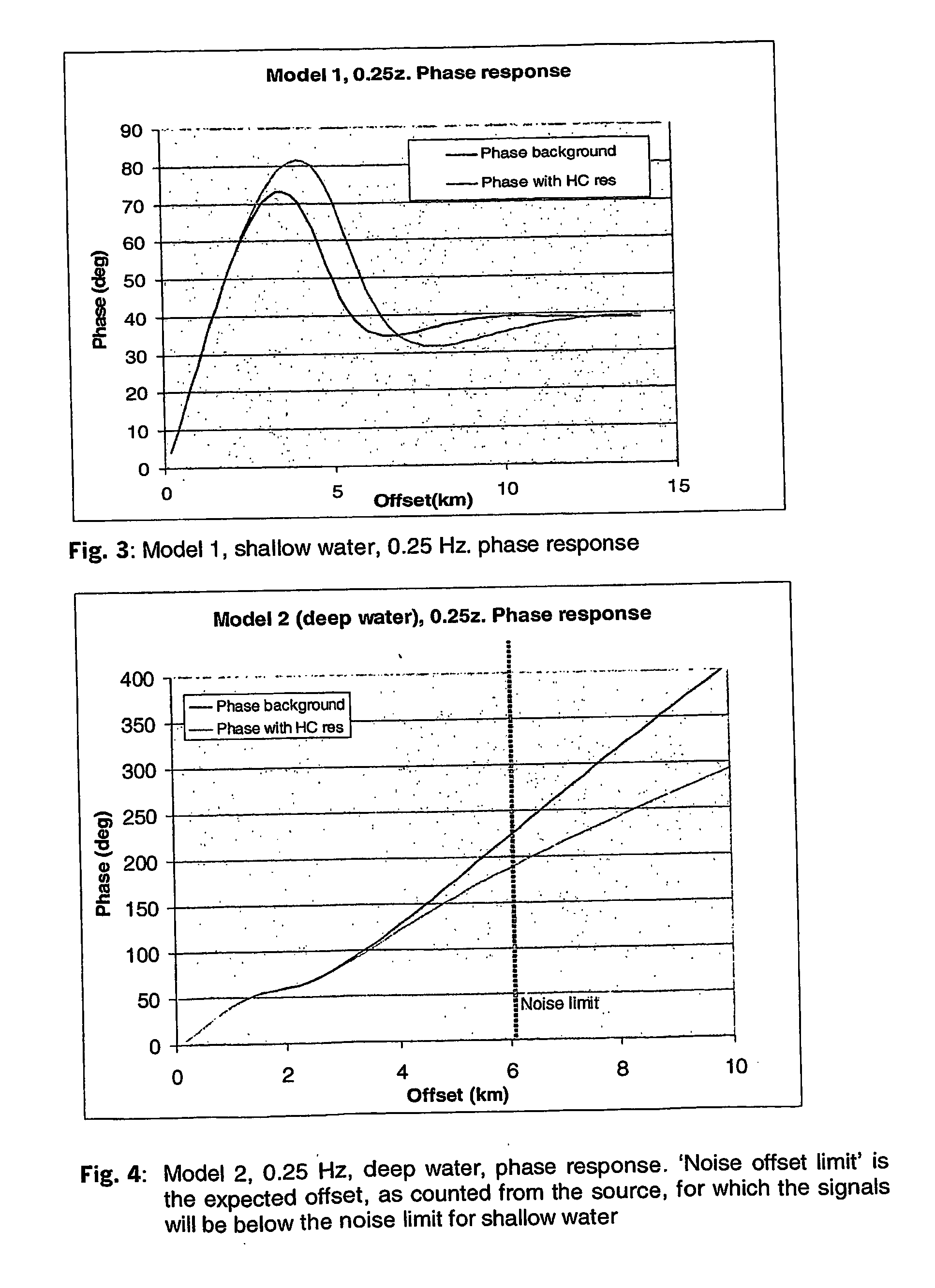
[0044]The work in connection to this invention has been focused on analysing different aspects of using a method according to the invention, seabed logging (SBL) in shallow water, and for testing a novel method for air wave subtraction for emphasising a reservoir response under such conditions.

[0045]The data acquisition itself may be conducted as follows: The emitted electromagnetic field F is an alternating field having frequencies in the range of 0.01 to 200 Hz. The emitted electromagnetic field F may in a preferred embodiment comprise frequencies in the range 0.1 to 1 Hz, e.g. 0.25 Hz. The measured component of the electromagnetic field F is preferably the electrical field E. A component of the electromagnetic field F to be measured may also be the magnetic field B.

[0046]The transmitter 5 to be used may comprise electrodes 50a, 50b arranged with a separation in the sea floor so as for forming an electrical dipole transmitter 5 but it may also comprise a magnetic transmitter. The ...


PUM


Abstract

A method for analysing acquired electromagnetic measurements (R) made at or in a sea (4) over a seafloor (1) with rock formations (3) having relatively low resistivity (ρ3) for detecting a possibly underlying petroleum bearing reservoir formation (2) having relatively high resistivity (ρ2), wherein a low frequency electromagnetic transmitter (5) arranged in the sea (4) emits an electromagnetic field (P) propagating in the sea (4), in the rocks (3, 2) and in the air (0) above the sea; wherein electromagnetic sensors (6) are arranged with desired offsets (x) in the sea (4) for measuring the electromagnetic field (P(x)) while the field propagates, characterized in that one or more component of the electromagnetic field (P) is measured at least one large offset (xL) from the transmitter (5) where the field (P) essentially only has its origin from the field propagating as a field (P0) through the air (0); that the one or more components of the electromagnetic field (P) measured at the large offset (xL) is calculated back to a recalculated field (F0(x)) to one or more offsets (x) being shorter than the large offset (xL); that the recalculated field (P0(X)) is subtracted from the field (P(x)) for possibly highlighting a field which arising due to the possibly petroleum bearing reservoir formation (2) having relatively high resistivity (ρ2).

Description

INTRODUCTION[0001]The invention relates to geophysics. More particularly the invention relates to electromagnetic geophysics at sea for detecting petroleum bearing rock strata in the geological rock layers below the seafloor.BACKGROUND OF THE INVENTION[0002]The rock layers below the seafloor will be water saturated and contain ions making the rocks electrically conductive, thus that provide high conductivity or low resistivity, ρ=0.7 to 3 Ωm. in this specification we will use the term resistivity, expressed in Ohm-meter abbreviated Ωm. Petroleum in the form of oil or gas displaces water in pore spaces of such petroleum bearing rock layers. Petroleum does not dissolve salts and is thus a weak electrical conductor, thus petroleum bearing rock layers provides a high resistivity, ρ=20 to 200 Ωm, and in some instances having a resistivity as high as 1000 Ωm. Sea water contains many different dissolved salts and usually has a resistivity of about 0.3 Ωm.STATEMENT OF PROBLEM AND PRIOR ART[...

Claims


Application Information

Patent Timeline
IPC IPC(8): G01V3/00
CPCG01V3/12G01V3/083Y02A90/30
Inventor WESTERDAHL, HARALDJOHNSTAD, SVEIN ERLINGFARRELLY, BRIAN ANTHONY
Owner MULTIFIELD GEOPHYSICS
Why Eureka
Try Eureka