
3D two-photon lithographic microfabrication system

a lithographic microfabrication and two-photon technology, applied in the field of multi-photon excitation microscopy/microfabrication, can solve the problems of insufficient long image acquisition or fabrication time, and inability to fully evaluate the depth discrimination capability of wide-field illumination system

Inactive Publication Date: 2009-11-12
MASSACHUSETTS INST OF TECH
View PDF15 Cites 17 Cited by
  • Summary
  • Abstract
  • Description
  • Claims
  • Application Information

AI Technical Summary

Benefits of technology

[0008]According to another aspect of the invention, there is provided a method of forming an imaging system. The method includes providing a optical pulse generator for providing an optical pulse having a spectral bandwidth and includes monochromatic waves having different wavelengths. Also, the method includes positioning a refractive dispersive element to receive a second optical pulse associated with the optical pulse and disperses

Problems solved by technology

It is common to implement laser scanning microscopy and laser writing microfabrication, but its major drawback is the longer image acquisition or fabrication time than that in the wide-field illumination based systems.
However, temporal focusing has never been applied to 3-D lithographic microfabrication.
In addition, depth discrimination capability for wide-field illumination system has not been fully evaluated both theoretically and empirically although it is one of the most important parameter in designing multiphoton wide-field illumination systems.

Method used


Image

  • 3D two-photon lithographic microfabrication system
  • 3D two-photon lithographic microfabrication system
  • 3D two-photon lithographic microfabrication system

Examples


Embodiment Construction

[0016]The invention proposes the design of a 3-D multiphoton lithographic system which generates 3-D microstructures with multiphoton wide-field illumination. This is the first time a microfabrication technique with multiphoton wide-field illumination is introduced. A mathematical model has been derived based on diffraction theory, to predict the axial resolution for both multiphoton wide-field illumination microscopy and microfabrication based on numerical simulation. Finally, the design parameters to improve axial resolution are reviewed. Future works include combining this optical model with a photopolymerization process model to predict fabrication efficiency and resolution.

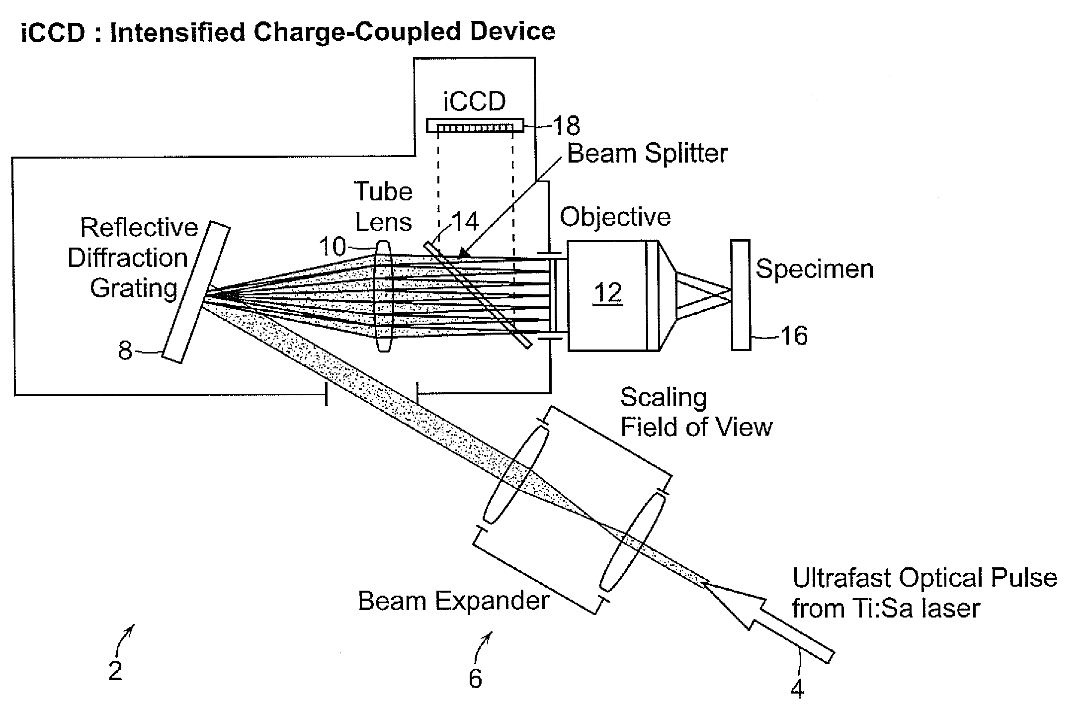
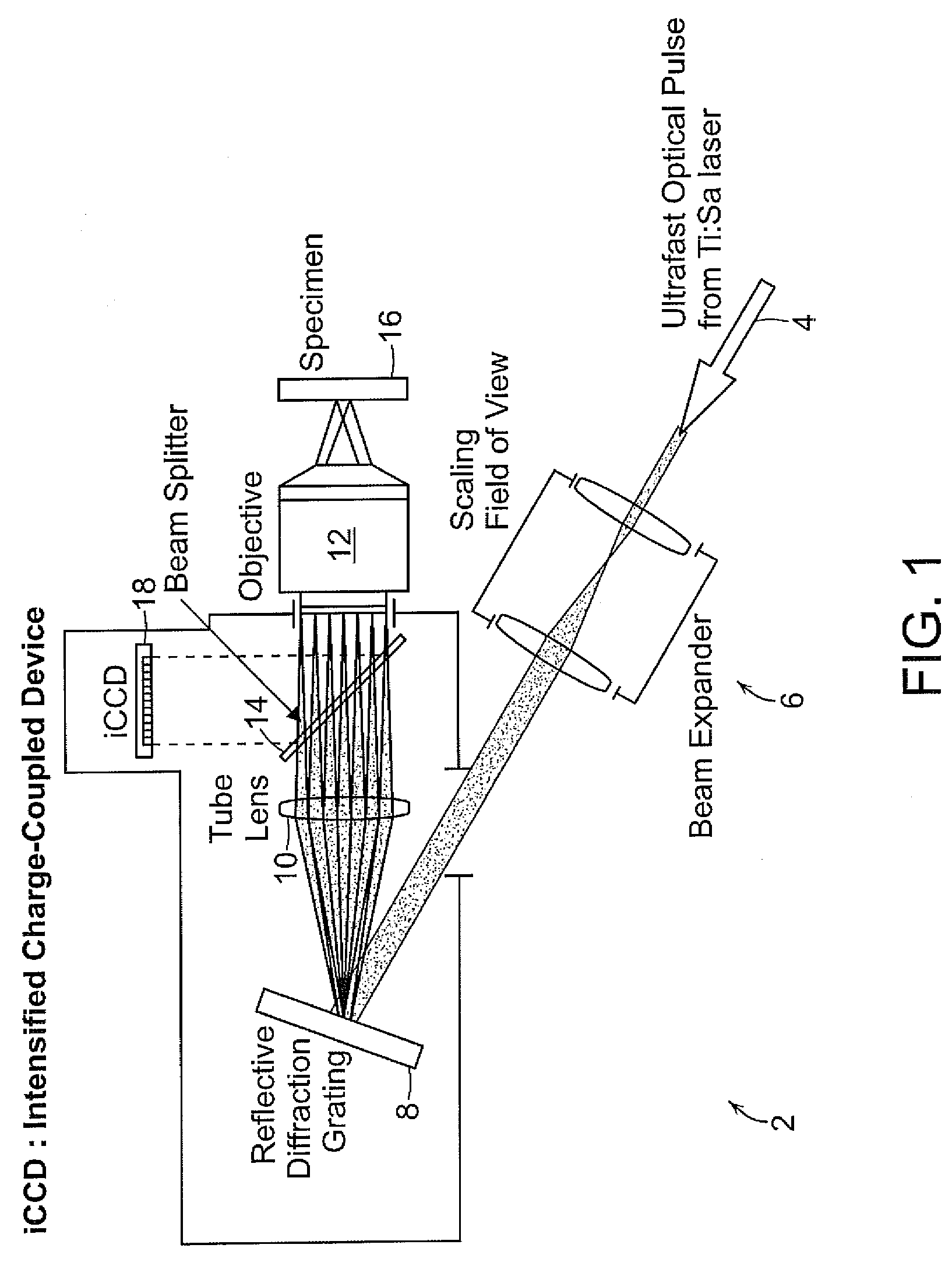
[0017]FIG. 1 shows a microscopic imaging system 2 based on depth-resolved widefield illumination. The microscopic imaging system 2 includes a 4-f imaging system and a reflective diffraction grating structure 8 acting as a dispersive element. If a mirror is located at the image plane instead of the reflective ...


PUM


Abstract

An imaging system is provided that includes a optical pulse generator for providing an optical pulse having a spectral bandwidth and includes monochiromatic waves having different wavelengths. A dispersive element receives a second optical pulse associated with the optical pulse and disperses the second optical pulse at different angles on the surface of the dispersive element depending on wavelength. One or more focal elements receives the dispersed second optical pulse produced on the dispersive element. The one or more focal element recombine the dispersed second optical pulse at a focal plane on a specimen where the width of the optical pulse is restored at the focal plane.

Description

PRIORITY INFORMATION[0001]This application claims priority from provisional application Ser. No. 61 / 048,284 filed Apr. 28, 2008, which is incorporated herein by reference in its entirety.SPONSORSHIP INFORMATION[0002]This invention was made with government support awarded by the U.S. Army Research Office under Contract No. W911NF-07-D-004 and the Department of Energy Computational Science Fellowship under Contract No. DE-FG02-97ER25308. The government has certain rights in the invention.BACKGROUND OF THE INVENTION[0003]The invention is related to the field of multiphoton excitation microscopy / microfabrication, and in particular to axial resolution for two-photon wide-field illumination microscopy and microfabrication.[0004]Multiphoton excitation fluorescence microscopy has recently gained popularity for cellular and tissue imaging. It provides intrinsic three-dimensional (3-D) resolution, allows deep imaging into tissues, achieves submicron optical resolution, and minimizes photodama...

Claims


Application Information

Patent Timeline
IPC IPC(8): G21G5/00
CPCG03F7/70375G03F7/2053
Inventor KIM, DAEKEUNSO, PETER T.C.
Owner MASSACHUSETTS INST OF TECH
Learn More