
Drive train for a vehicle with connectable secondary axle

a technology of drive train and secondary axle, which is applied in the direction of vehicle components, control devices, transportation and packaging, etc., can solve the problems of affecting the operation the tension of the drive train, and the complexity of the drive train structural aspect, so as to reduce the additional structural cost, minimize the power loss, and improve the effect of operating comfort and suitability for daily us

Active Publication Date: 2009-11-12
GETRAG DRIVELINE SYST +1
View PDF6 Cites 64 Cited by
  • Summary
  • Abstract
  • Description
  • Claims
  • Application Information

AI Technical Summary

Benefits of technology

[0011]The aim of the invention is therefore to further develop a drive train of the type initially specified such that when the secondary axle is uncoupled, power loss is minimized. A further aim of the invention is to reduce the additional structural cost and the associated extra weight of a vehicle with connectable secondary axle, despite the possibility of longitudinal equalization between primary and secondary axle and the possibility of transverse equalization on the secondary axle. At the same time a drivable secondary axle should be provided which can be switched on automatically during travel, in particular also at higher speeds. Compared to manually connectable wheel hub couplings operating comfort and suitability for daily use in particular should be increased.
[0013]When the secondary drive train is connected both the side shaft couplings and the switch-on device are coupled, enabling the secondary drive output flow from the primary axle to the secondary axle drive wheels. When the secondary drive train is disconnected both the side shaft couplings and the switch-on device are uncoupled, so that when the secondary axle is uncoupled the section of the secondary drive train located between the switch-on device and the side shaft couplings is uncoupled both from the drive power and from the drive wheels of the secondary axle. At the same time the effort should be made to shut down as many components as possible. Other measures which reduce power loss are also significant.
[0014]This configuration of the drive train makes it possible to completely shut down a majority of the secondary drive train with the secondary axle uncoupled. The drive train components belonging to the shutdown section of the secondary axle drive train consequently cause no power loss. Frictionally engaged couplings are provided particularly to match the speed of both components of the secondary drive train uncoupled from the vehicle drive and from the drive wheels of the secondary axle prior to incorporating in the whole drive train at the speed of the non-uncoupled components of the drive train.
[0016]With this type of axle drive without differential, in addition to simultaneous transverse and longitudinal equalization other functions are also conceivable, such as that of an active-yaw differential, in which a yawing moment can be produced specifically by the individual actuation of the couplings. Any limit values can also be shown by the individually adjustable side shaft couplings, so that the functions of limit differential can also be realized. Omitting a plurality of otherwise necessary drive train components (wheel hub switching, transverse and longitudinal differential) makes a cost-optimized and weight-optimized configuration of the drive train possible.
[0018]The positive power transmission gearbox must of course be synchronized for the switching procedures to be provided, therefore in particular the coupling or respectively uncoupling of the secondary drive train. Such speed synchronization can be readily guaranteed on the one hand by means of gearbox synchronization familiar to the expert. The power transmission gearbox however is preferably synchronized by the side shaft couplings to create the tight fit. If the part of the secondary drive train located between the side shaft couplings and the switch-on device for transmitting part of the available overall drive output to the secondary axle were to be switched to the whole drive train, the secondary drive train, which is then powered by the drive wheels rolling way on the street, can be graduated to switching speed and thus speed synchronization can be executed by coupling the side shaft couplings. After the synchronization speed is reached the tight fit can be made by switch-on mechanism of the switch-on device. Even if conventional synchronization were not to be omitted despite such speed matching, synchronization can be supported by the frictionally engaged side shaft couplings being lightly closed prior to coupling of the secondary drive train. Synchronous forces accordingly drop out slightly. Components can be dimensioned for lesser loads, also an advantage for the lifetime of the components.
[0019]It can also be provided that the side shaft couplings are formed by a frictionally engaged multiple disc clutch, whereby the friction plates connected torque-proof to the secondary drive wheels cooperate with an inner plate carrier and the vehicle drive-side discs cooperate with an outer plate carrier. This configuration enables the particularly energy-efficient use of an on-demand lubricating of the clutch packs without additional, external oil supply. The clutch housing forms an oil sump filled with lubricating and cooling oil, in which the coupling discs plunge. If the outer plate carrier rotates it takes the oil along with it on its exterior and delivers it to an oil circuit. This oil supply output afflicted with power loss is canceled whenever the outer plate carrier does not rotate when the coupling is open. This is possible however only if the outer plate carrier forms part of the shut-down section of the secondary drive train.

Problems solved by technology

Switching during driving is mostly not an option due to unavailable speed synchronization of the positively engages power transmission elements or if so is possible only at minimal speeds.
First, care should be taken that the drive wheels of the primary axle and the drive wheels of the secondary axle in particular travel different trajectories when driving round curves, but also in other operational situations, which without a corresponding speed difference balance would lead to tensions in the drive train.
As compared to a vehicle which is fitted exclusively with a permanently driven primary axle, these additional system components to be provided make the drive train clearly more complex in the structural aspect.
Vehicle costs in development and construction are clearly higher as a result.
The larger number of required components also makes such a drive train expensive and contributes to more weight, in turn resulting in increased fuel consumption.
In addition, countless factors diminish the net drive output actually available in operation, therefore that part of the overall drive-side available drive output, which actually can be utilized for propelling the vehicle, and also whenever the secondary axle not is connected.
This gives rise to friction losses (bearing friction, churning losses, friction of gearwheel engagement, etc.) and the rotating masses of the secondary driven train components (differential, intermediate shaft, couplings, etc.) are to be accelerated or respectively relented constantly with the vehicle during dynamic driving.
This power loss contributes significantly to the fact that fuel consumption in a vehicle with connectable secondary axle even with uncoupled secondary axle is noticeably higher than in a vehicle having no drivable secondary axle.
Clients wanting a vehicle which provides a selectively connectable secondary axle must consider increased consumption however, even if they barely make use of connecting.

Method used


Image

  • Drive train for a vehicle with connectable secondary axle
  • Drive train for a vehicle with connectable secondary axle
  • Drive train for a vehicle with connectable secondary axle

Examples


Embodiment Construction

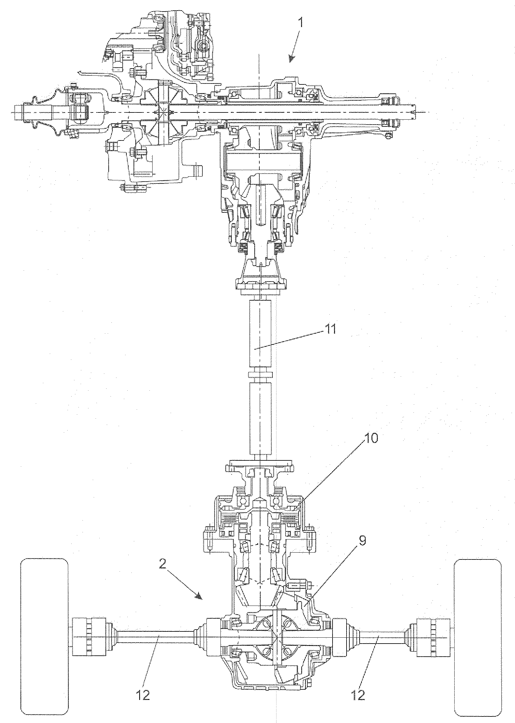
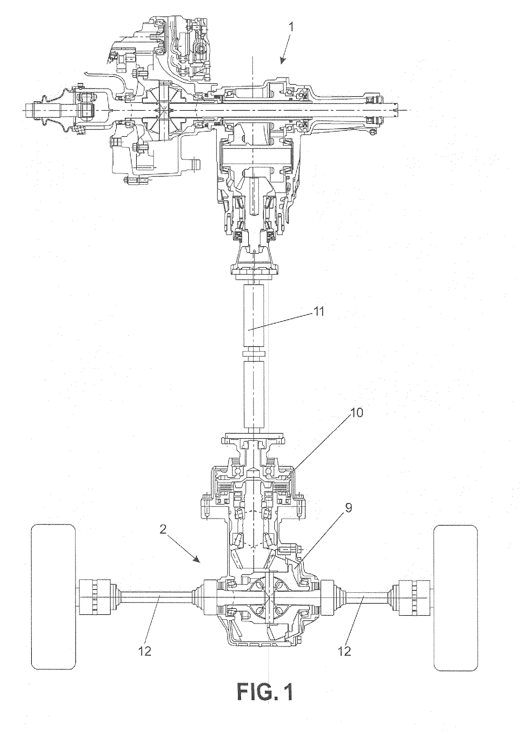
[0039]FIG. 1 shows a drive train of a vehicle, which is known from the prior art with respect to its functional principle. The primary axle 1 is permanently driven. A non-switchable angular gear branches part of the drive power off from the primary axle and supplies it to the secondary drive train serving to drive the secondary axle 2. Provided in front of the axle drive unit 9 is a hang-on coupling 10 which in the closed state connects an intermediate shaft 11 and the axle drive unit 9 non-positively and is thus able to convey the secondary drive train output as required to the axle drive unit 9. The axle drive unit 9 has a conventional structure and has a bevel gear differential to which the secondary side shafts 12 attach.

[0040]FIG. 2 shows a drive train of a vehicle, the functional principle of which is likewise known from the prior art. In contrast to FIG. 1 the axle drive unit 9 is not connected to the intermediate shaft 11 via a switchable coupling, but the intermediate shaft...


PUM


Abstract

The invention relates to a drive train of a vehicle, comprising a permanently driven primary axle and a secondary axle connectable to the primary axle via a switch-on device with a switch-on mechanism, whereby the secondary drive train output via side shaft couplings is transferred to the drive wheels of the secondary axle.A disadvantage to these drive trains is that also when the secondary axles are not connected their components are dragged along by the vehicle drive or by the drive wheels rolling away on the roadway, causing power losses. Complete shutdown of the secondary drive train to date is executed only by manually switchable wheel hub couplings which are however a disadvantage with respect to ease of use and practicability.Because the switch-on mechanism and / or the side shaft couplings have frictionally engaged couplings, it can be that when the secondary axle is uncoupled the section of the secondary drive train located between the switch-on device and the side shaft couplings is uncoupled both from the primary axle and from the secondary drive wheels, such that there is no more power loss in this secondary drive train section, whereby connecting the secondary drive train during travel is possible all the same and losses in comfort and practicability do not have to be tolerated.

Description

CROSS-REFERENCE TO RELATED APPLICATIONS[0001]The present application claims priority to German Patent Application No. 10 2008 002 844.4 filed on May 6, 2008 and German Patent Application No. 10 2008 057 272.1 filed on Nov. 13, 2008.STATEMENT RE: FEDERALLY SPONSORED RESEARCH / DEVELOPMENT[0002]Not applicable.[0003]1. Technical Field of the Invention[0004]The invention relates to a drive train of a vehicle, comprising a primary axle permanently driven by a primary drive train and a secondary axle connectable to the primary axle by a switch-on device, which can be driven by a secondary drive train, whereby the switch-on device has a switch-on mechanism via which the secondary drive train can be integrated in the drive train transferring the overall drive output, and whereby the secondary drive train output is conveyed via side shaft couplings into side shafts of the secondary axle when the secondary axle is connected and is transferred to drive wheels of the secondary axle.[0005]2. Descr...

Claims


Application Information

Patent Timeline
Patent Type & Authority Applications(United States)
IPC IPC(8): B60K23/08
CPCB60K23/0808B60K2023/043
Inventor HOFFMANN, WERNERNETT, HANS-PETERHOECK, MICHAELPOTULSKI, JANADELT, MATTHIAS
Owner GETRAG DRIVELINE SYST
Learn More