
Method and apparatus for producing a crucible of quartz glass

a technology of quartz glass and crucible, which is applied in the direction of glass making apparatus, glass growth process, glass shaping apparatus, etc., can solve the problems of high construction cost, high energy and process gas consumption, and low yield of dislocation-free silicon single crystal, so as to achieve low energy and material consumption

Inactive Publication Date: 2009-11-12
HERAEUS QUARZGLAS
View PDF6 Cites 13 Cited by
  • Summary
  • Abstract
  • Description
  • Claims
  • Application Information

AI Technical Summary

Benefits of technology

The present invention provides a method for producing a quartz glass crucible with a low-bubble inner layer while keeping the energy and material consumption low. This is achieved by forming a granule layer consisting of SiO2 inner layer granules on the inner wall of the crucible or the crucible base mold, and then vitrifying this layer during the vitrification step. The plasma zone and heat shield are movable at least once during the vitrification to locally heat and vitrify the granule layer. The use of a horizontally movable heat shield and a continuously or periodically directed gas inlet further reduces energy consumption. The method is simple and efficient in producing transparent inner layers with a low amount of bubbles.

Problems solved by technology

In this pulling process, the quartz glass crucible is subjected to high mechanical, chemical and thermal loads for several hours.
During the intended use of the crucible these bubbles will grow under the action of temperature and pressure and will finally burst so that fragments and other impurities pass into the silicon melt, resulting in a lower yield of dislocation-free silicon single crystal.
In the known method the manufacture of a bubble-free inner layer entails a comparatively high consumption of energy and process gases and requires high constructional efforts.

Method used


Image

  • Method and apparatus for producing a crucible of quartz glass
  • Method and apparatus for producing a crucible of quartz glass

Examples


Embodiment Construction

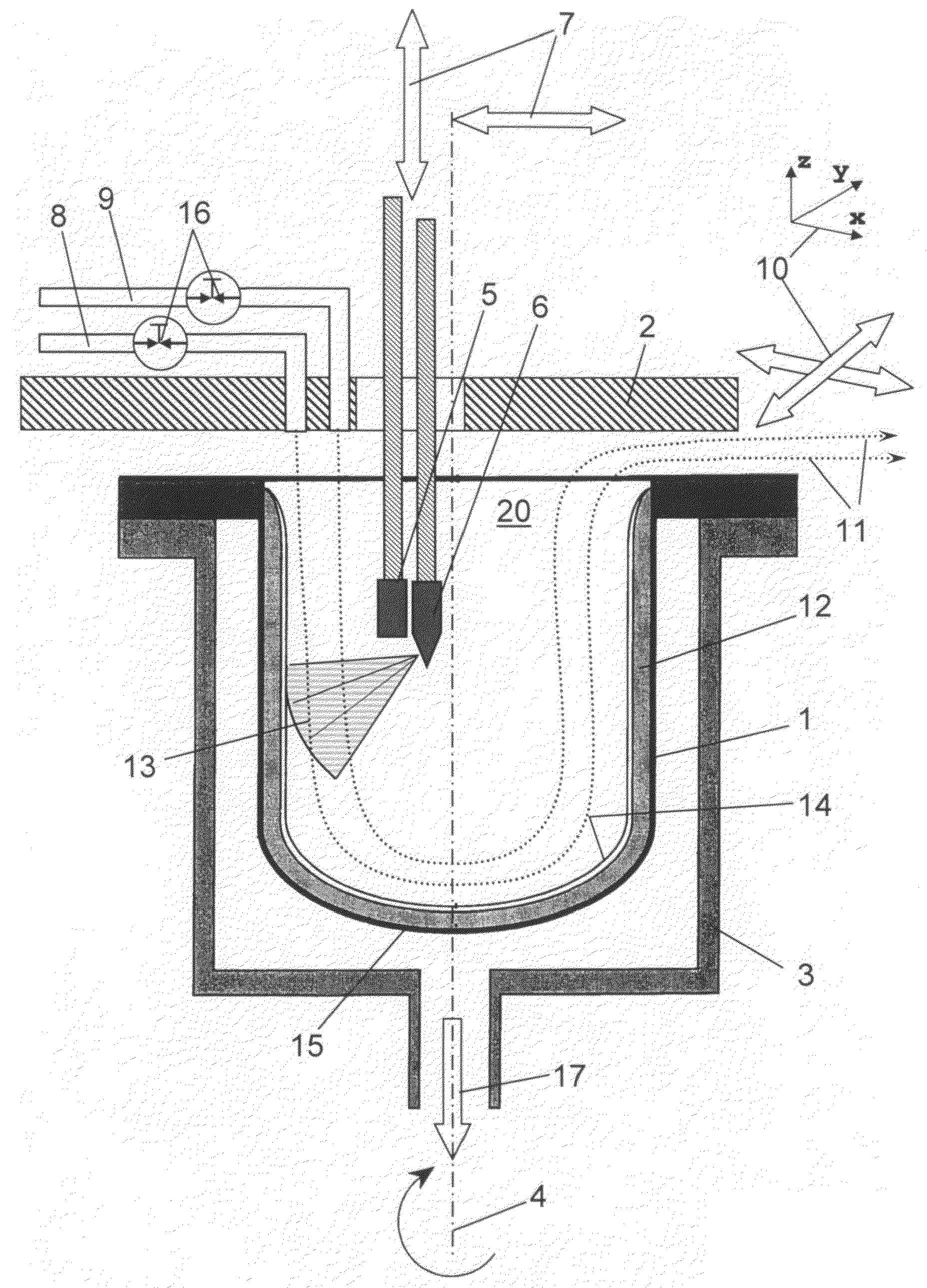
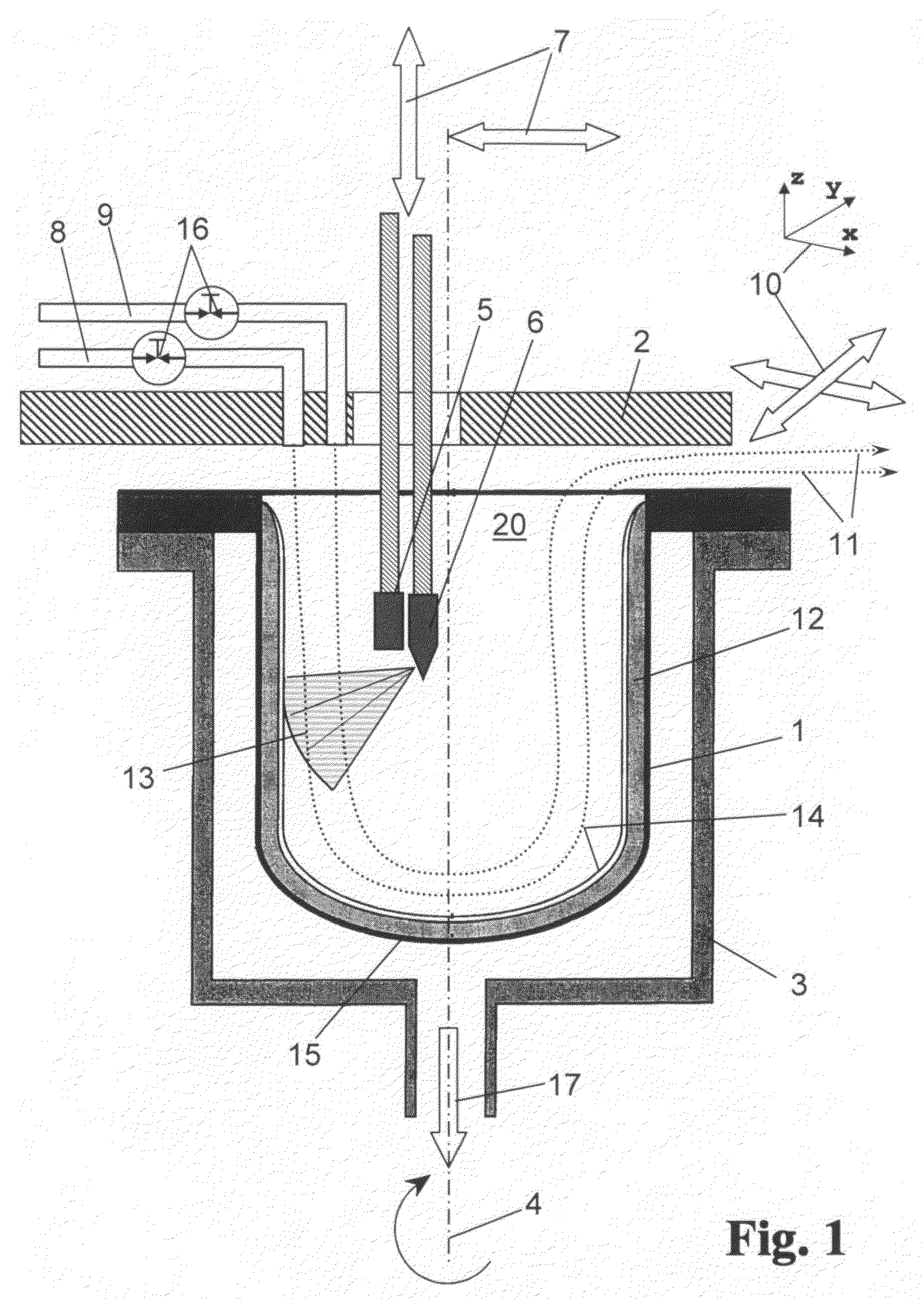
[0054]The melting apparatus according to FIG. 1 comprises a melting mold 1 of metal with an inner diameter of 75 cm, the mold 1 resting with an outer flange on a support 3. The support 3 is rotatable about the central axis 4. A cathode 4 and an anode 6 (electrodes 5; 6) of graphite which, as illustrated by way of directional arrows 7, are movable inside the melting mold 1 in all spatial directions project into the interior 20 of the melting mold 1.

[0055]A heat shield 2 in the form of a water-cooled metal plate having a thickness of 10 mm, which comprises a central through-hole through which the electrodes 5, 6 protrude into the melting mold 1 projects beyond the open upper side of the melting mold 1. The heat shield 2 is connected to a gas inlet 8 for a gas mixture of helium and oxygen and to a gas inlet 9 for pure helium, which inlets are configured as flexible pipes into which gas flow controllers 16 (MFC) are inserted. A venting gap with a width of 50 mm is provided between the m...


PUM

PropertyMeasurementUnit
inner diameteraaaaaaaaaa
thicknessaaaaaaaaaa
widthaaaaaaaaaa

Abstract

The invention starts from a method for producing a crucible of quartz glass in that SiO2 inner layer granules are vitrified in a rotating melting mold, which is covered at least in part by a heat shield, in a light gas-containing atmosphere under the action of a plasma to obtain a transparent inner layer, at least part of the light gas being supplied to the melting mold through a gas inlet of the heat shield. In order to form an inner layer with a particularly low bubble content and with minimal efforts in terms of energy and material, it is proposed that in a layer forming step preceding the vitrifying step a granule layer consisting of the SiO2 inner layer granules is formed on the inner wall of the crucible, and that the plasma zone and the heat shield are movable together with the gas inlet and are moved laterally in the direction of the granule layer during the vitrifying step taken for vitrifying the granule layer.

Description

FIELD OF THE INVENTION [0001]The present invention relates to a method for producing a crucible of quartz glass, the method comprising a method step of vitrifying SiO2 inner layer granules by vitrifying said granules in a melting mold which rotates about an axis of rotation and comprises an inner wall and an upper side opening covered by a heat shield at least in part, under the action of a plasma zone in a light gas-containing atmosphere with formation of a transparent inner layer on a crucible base mold of quartz glass, wherein at least part of the light gas is supplied to the melting mold through a gas inlet of the heat shield.DESCRIPTION OF THE RELATED ART[0002]Quartz glass crucibles are used for receiving the metal melt while single crystals are pulled according to the so-called Crzochralski method. In this pulling process, the quartz glass crucible is subjected to high mechanical, chemical and thermal loads for several hours. To mitigate the corrosive attack of the metal melt ...

Claims


Application Information

Patent Timeline
Patent Type & Authority Applications(United States)
IPC IPC(8): C03B20/00C03C10/00
CPCC03B19/095C30B35/002C30B15/10
Inventor KAYSER, THOMASLEHMANN, WALTERLAUDAHN, HILMAR
Owner HERAEUS QUARZGLAS
Learn More