Eureka AIR delivers breakthrough ideas for toughest innovation challenges, trusted by R&D personnel around the world.

Azimuthal Elemental Imaging

a technology of elemental imaging and azimuthal elements, applied in seismology for waterlogging, instruments, reradiation, etc., can solve the problem of providing little or no information about the formation mineral composition

Active Publication Date: 2009-11-05
BAKER HUGHES INC
View PDF20 Cites 30 Cited by
  • Summary
  • Abstract
  • Description
  • Claims
  • Application Information

AI Technical Summary

Problems solved by technology

A drawback of these imaging methods is that while they reveal structural information about the earth formation, they provide little or no information about the formation mineral composition.

Method used


Image

  • Azimuthal Elemental Imaging
  • Azimuthal Elemental Imaging
  • Azimuthal Elemental Imaging

Examples


Embodiment Construction

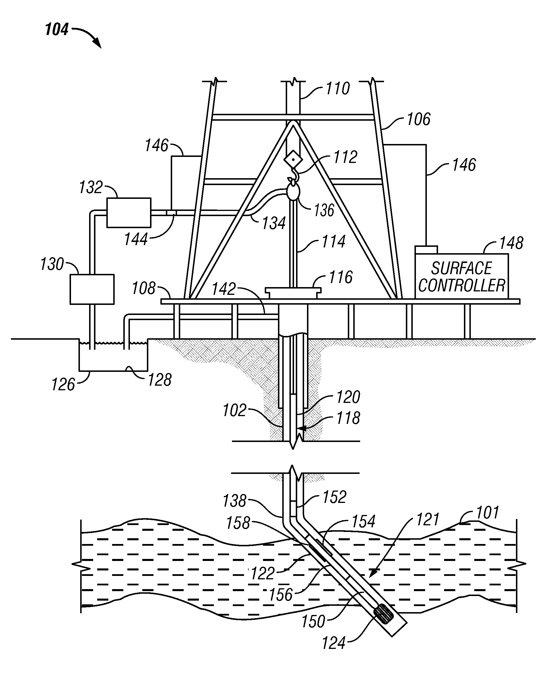
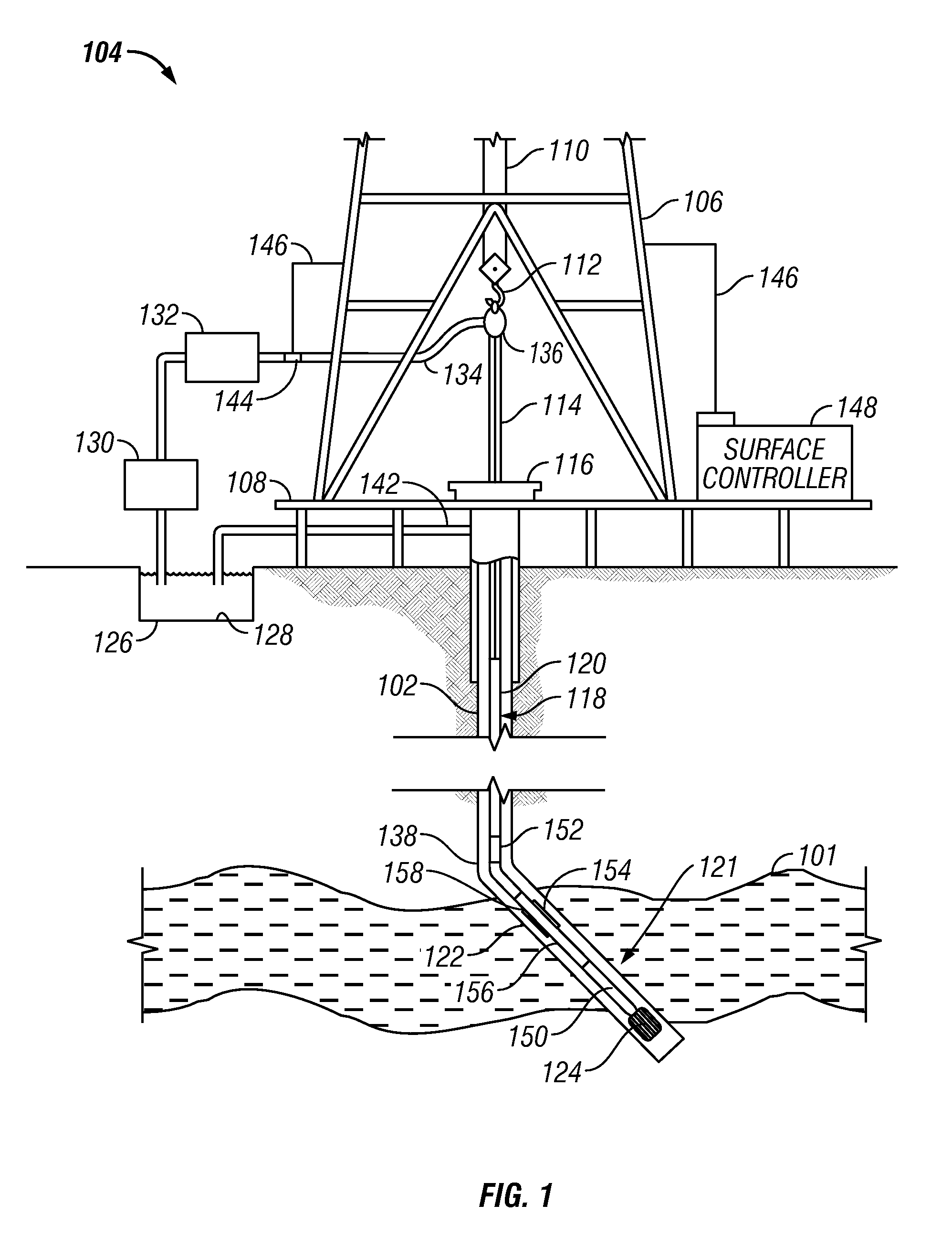
[0022]FIG. 1 is an elevation view of a simultaneous drilling and logging system that incorporates an embodiment of the present disclosure. A borehole 102 is drilled into the earth under control of surface equipment including a rotary drilling rig 104. In accordance with a conventional arrangement, rig 104 includes a derrick 106, derrick floor 108, draw works 110, hook 112, kelly joint 114, rotary table 116, and drill string 118. The drill string 118 includes drill pipe 120 secured to the lower end of the kelly joint 114 and to the upper end of a section comprising a plurality of drill collars. The drill collars include not separately shown drill collars such as an upper drill collar, an intermediate sub drill collar, and a lower drill collar bottomhole assembly (BHA) 121 immediately below the intermediate sub. The lower end of the BHA 121 carries a downhole tool 122 of the present disclosure and a drill bit 124.

[0023]Drilling fluid 126 is circulated from a mud pit 128 through a mud ...


PUM


Abstract

Measurements made by a wireline-conveyed pulsed neutron tool with two or more gamma ray detectors are used to provide a mineralogical and / or elemental image of the formation. This may be used in reservoir navigation and in furthering the understanding of the geology of the prospect.

Description

CROSS-REFERENCES TO RELATED APPLICATIONS[0001]This application is a continuation-in-part of U.S. patent application Ser. No. 11 / 936,203 filed on Nov. 7, 2007, the contents of which are incorporated herein by reference. The application is also related to an application titled “Azimuthal Elemental Imaging”, having Andrew Kirkwood, Philip Kurkoski and Richard Pemper as inventors filed concurrently with the present application under Attorney Docket 594-42749-USCP1 the contents of which are incorporated herein by reference.FIELD OF THE DISCLOSURE[0002]The present disclosure relates generally to devices, systems, and methods of geological exploration in wellbores. More particularly, the present disclosure describes a device, a system, and a method useful for producing a lithology image of an earth formation in a borehole during drilling.BACKGROUND OF THE DISCLOSURE[0003]A variety of techniques are currently utilized in determining the presence and estimation of quantities of hydrocarbons ...

Claims


Application Information

Patent Timeline
IPC IPC(8): G01V5/10G06F19/00G01V5/12
CPCG01V5/125G01V5/101
Inventor KIRKWOOD, ANDREW D.KURKOSKI, PHILIP L.
Owner BAKER HUGHES INC
Why Eureka
Eureka Blog
Learn More