
Radiation shield concrete and preparation method thereof

A concrete and radiation protection technology, applied in the field of building materials, can solve the problems such as barite and lead powder cannot be widely used, the chemical composition of steel slag is inconsistent, and the ability to protect against neutron rays is poor. The effect of reducing the water-cement ratio

Inactive Publication Date: 2011-10-19
WUHAN UNIV OF TECH
View PDF6 Cites 58 Cited by
  • Summary
  • Abstract
  • Description
  • Claims
  • Application Information

AI Technical Summary

Problems solved by technology

However, since this method does not use high-density anti-radiation aggregates, the purpose of shielding radiation must be achieved by increasing the thickness of the concrete, and the ability of the concrete to protect against neutron radiation is relatively poor.
[0007] Patent No. CN101805156A discloses a method for preparing anti-radiation concrete using steel slag sand and barite as coarse aggregate, but the coarse aggregate used in the anti-radiation concrete prepared by this method is steel slag and barite, because the steel slag in different places Inconsistent chemical composition, which affects the durability of concrete
And because barite is brittle, mechanical stirring will cause it to break into powder. Therefore, in order to reduce crushing in actual construction, we can only strictly control the mixing time, which may lead to uneven mixing of concrete, and barite resources are scarce, so has its limitations
[0008] Patent No. CN100999401A uses barite and lead powder to improve radiation protection performance. It also needs to control the construction process. Barite and lead powder cannot be widely used, so there are limitations

Method used


Image

  • Radiation shield concrete and preparation method thereof
  • Radiation shield concrete and preparation method thereof
  • Radiation shield concrete and preparation method thereof

Examples

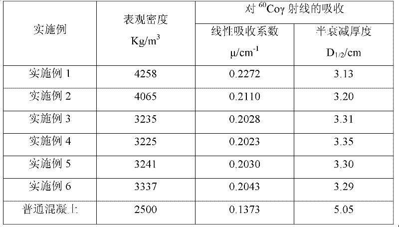
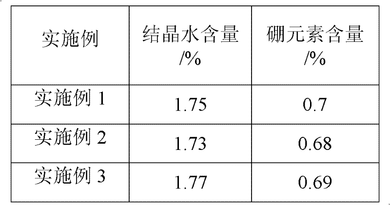

Embodiment 1~6

[0027] Embodiment 1~6 a kind of preparation method of radiation-proof concrete

[0028] 1) to prepare 1m 3 Take radiation-proof concrete as an example, select raw materials according to the ratio in Table 1, and the details of each raw material are as follows:

[0029] Cement: Choose 42.5 grade ordinary Portland cement.

[0030] Inorganic mineral admixture: fly ash is ordinary secondary ash; silicon powder is ordinary silicon powder, with a specific surface area of ​​150,000-250,000m 2 / kg;

[0031] Coarse aggregate: steel segment, cylindrical shape, particle size 5-18mm, diameter 3-8mm, maximum length no more than 15-20mm, apparent density 7500kg / m 3 ;Steel slag: Egang steel slag with stable quality (mass loss ≤ 5%) after being stored for one year and tested for stability by steaming (refer to the national standard "Steel slag powder used in cement and concrete (GB / T 20491-2006)") , gradation 5-20mm, apparent density 2912kg / m3, bulk density 1743kg / m3 3 , the water absorp...


PUM

PropertyMeasurementUnit
Specific surface areaaaaaaaaaaa
Particle sizeaaaaaaaaaa
Diameteraaaaaaaaaa

Abstract

The invention relates to radiation shield concrete and a preparation method thereof. The radiation shield concrete is characterized by comprising a cementing material, coarse aggregates, fine aggregates, steel fibre, a high-efficiency slushing agent and water; the cementing material is composed of ordinary portland cement and inorganic mineral admixtures; the inorganic mineral admixtures are siliceous dust and coal ash; the fine aggregates are natural sand, boron glass powder and steel slag powder; the coarse aggregates are steel sections or a mixture of the steel sections and steel slag; the proportions of various types of components are as follows: 500 kg / m<3> of cementing material, 1400-2215 kg / m<3> of coarse aggregates, 750-950 kg / m<3> of fine aggregates, and 155-200 kg / m<3> of water; the high-efficiency slushing agent is 0.5-1.0% of the total weight of the cementing material by weight; and the steel fibre is 1.0-1.5% of the total volume of the concrete by volume. The radiation shield concrete has good mechanical property and lasting quality, good shielding effect on gamma rays, good effect on shielding neutron rays, can be used or comprehensively recycling wastes and has low cost.

Description

Technical field: [0001] The invention belongs to the field of building materials, and in particular relates to a radiation-proof concrete and a preparation method thereof. Background technique: [0002] Nuclear technology has developed rapidly since its birth, and has been widely used in many fields such as nuclear power, military, education, scientific research, and medical treatment. However, its safety has always been the key to its further development. As we all know, a large amount of radiation produced by nuclear reactions can induce cancer, leukemia and multiple myeloid cancer, large breast cancer, infertility, miscarriage and birth defects and other terminal human diseases, as well as induce genetic mutations in plants and endanger the growth of crops. [0003] Radiation-resistant concrete is also known as radiation-resistant concrete, atomic energy shielding concrete, shielding concrete, nuclear reactor concrete, or heavy concrete. As a protective material for nucl...

Claims


Application Information

Patent Timeline
IPC IPC(8): C04B28/04G21F1/04
CPCC04B28/04Y02W30/91C04B14/02C04B14/48C04B18/08C04B18/146C04B20/0096C04B40/0028C04B40/0067C04B2103/302C04B14/068C04B14/22C04B14/34C04B18/141C04B20/0076
Inventor 陈友治宋正林李国刚李儒光叶换新叶剑梁三标曹晓梅林家超
Owner WUHAN UNIV OF TECH
Learn More