
Cursor Input Device With Dual Input Modes

a technology of input device and input mode, applied in the field of input device of cursor, can solve the problem that the manufacturing cost will not be doubled

Inactive Publication Date: 2009-10-29
WALTOP INT
View PDF8 Cites 49 Cited by
  • Summary
  • Abstract
  • Description
  • Claims
  • Application Information

AI Technical Summary

Benefits of technology

[0006]The primary object of the present invention is to provide a cursor input device with dual input modes. The dual input modes are finger touch and the electromagnetic pen, so that a single cursor input device can uses suitable input mode according to the type of application. In addition, the cursor input device of the present invention can automatically select the respective signal processing process according to the input mode so that the user does not need to manually switch to different input mode.
[0007]Another object of the present invention is to provide a cost-effective cursor input device. While the cursor input device has two input modes, the manufacturing cost will not be doubled. The manufacturing cost of the present invention will comparable to the manufacturing cost of the conventional digital board. Therefore, the present invention is cost effective and more market competitive.
[0008]Yet another object of the present invention is to provide a cursor input device applicable to a wider range of applications and more convenient to use. The present invention can be integrated with software and firmware to provide better performance and efficiency. For example, in an application, a user can use finger to draw or sketch a draft in a fast and convenient manner and then uses the electromagnetic pen for precise drawing or refining the sketched draft. Or, the designer can utilize the advantage of each input mode so that different usages can be defined in the product to allow the user more flexible operation. For example, when using computer in web browsing or searching, the touch input mode can be used, while in the precise graphical design or writing recognition, the electromagnetic pen input mode can be automatically switched to.

Problems solved by technology

While the cursor input device has two input modes, the manufacturing cost will not be doubled.

Method used


Image

  • Cursor Input Device With Dual Input Modes
  • Cursor Input Device With Dual Input Modes
  • Cursor Input Device With Dual Input Modes

Examples


Embodiment Construction

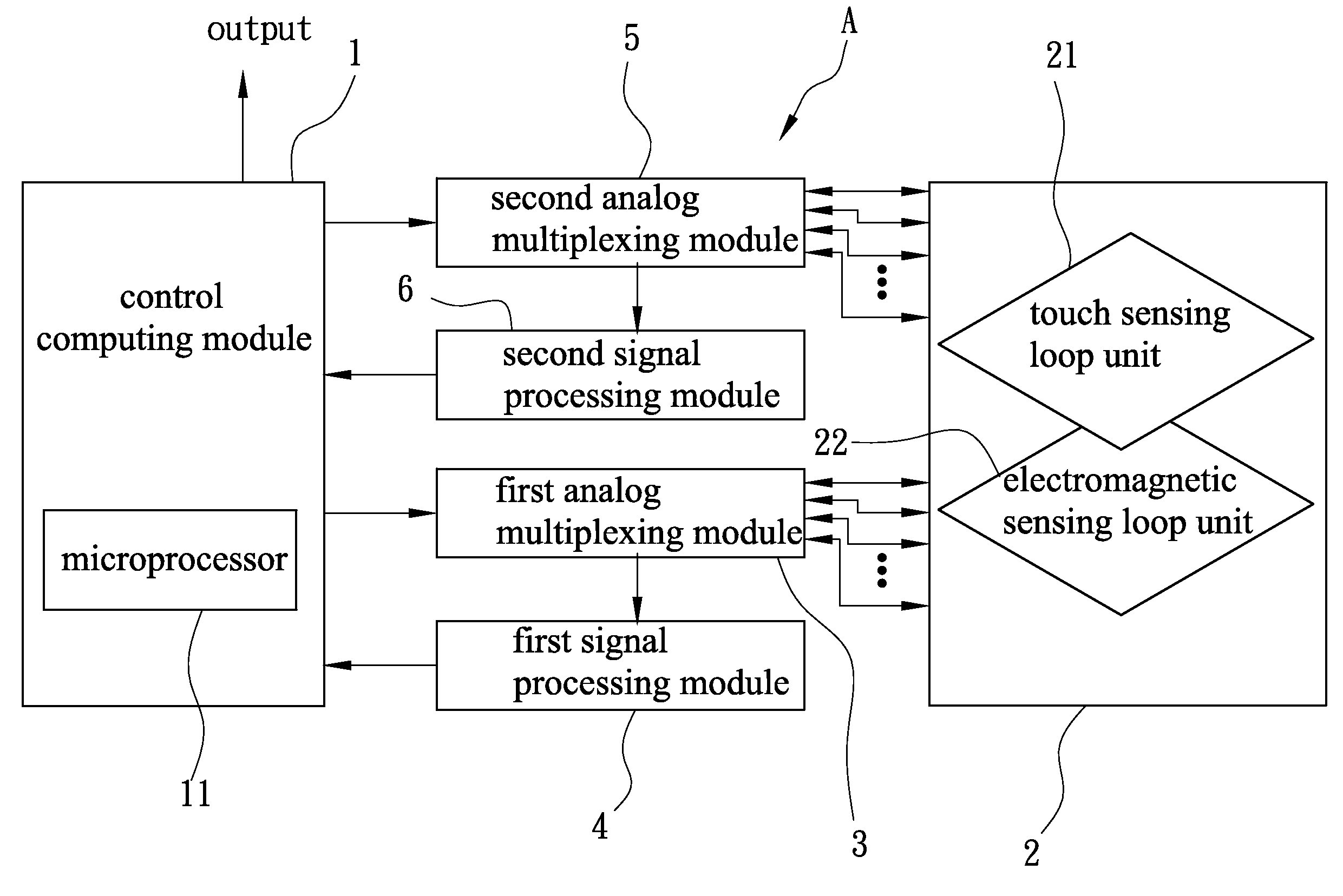
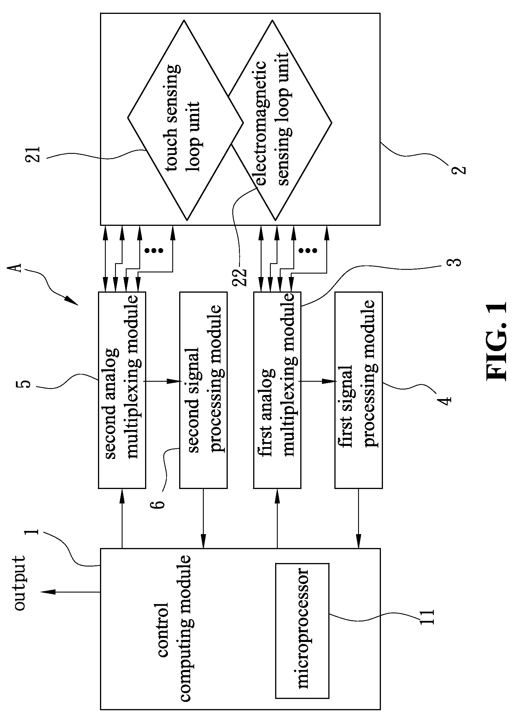
[0018]FIG. 1 shows a block diagram of a cursor input device with dual input modes of the present invention. As shown in FIG. 1, a cursor input device A includes a control computing module 1, a coordinate sensing module 2, a first analog multiplexing module 3, a first signal processing module 4, a second analog multiplexing module 5, and a second signal processing module 6. Coordinate sensing module 2 can accept the input either by finger touch or electromagnetic pen. Control computing module 1 uses analog multiplexing modules to scan the signal input by finger touch or the electromagnetic pen, and then the signal processing modules process the sensed signal. The processed signals are computed and output by microprocessor 11 of control computing module. Therefore, cursor input device A of the present invention can accept two different input modes.

[0019]The following describes the details of the components. Coordinate sensing module 2 includes a touch sensing loop unit 21 and an elect...


PUM


Abstract

A cursor input device with dual input modes is provided, including a control computing module, a coordinate sensing module, a first analog multiplexing module, a first signal processing module, a second analog multiplexing module and a second signal processing module, where the coordinate sensing module further including a touch sensing loop unit and an electromagnetic sensing loop unit. The control computing module at least includes a microprocessor. The control computing module uses the first analog multiplexing unit and the first signal processing module to enable the electromagnetic sensing loop unit to perform signal scanning and processing, and uses the second analog multiplexing unit and the second signal processing module to enable the touch sensing loop unit to perform signal scanning and processing. In this manner, the user can use either touch input mode or electromagnetic pen input mode to control the cursor of the present invention to execute various the application software or operating system.

Description

FIELD OF THE INVENTION[0001]The present invention generally relates to a cursor input device, and more specifically to a cursor input device with both electromagnetic pen and touch panel modes.BACKGROUND OF THE INVENTION[0002]The continuous progress in touch panel technology lowers the manufacture cost and enables the wide range of applications of touch panels. For example, the information kiosk at public locations, ATM machines, thin notebook PC, tablet PC, PDA, electronic dictionary, mobile phone, MP3 player and GPS.[0003]Two major categories of touch panel technologies are used. The first category is the resistor-based, and the second category is the capacitor-based. The resistor-based touch panel is based on the pressure generated by the touch on the panel so that the upper layer conductive membrane and the lower layer conductive membrane contact and the voltage drops. The touch point of the pressure can then be calculated to obtain the X-axis and Y-axis. This is the most popula...

Claims


Application Information

Patent Timeline
Patent Type & Authority Applications(United States)
IPC IPC(8): G06F3/041
CPCG06F3/044G06F2203/04106G06F3/046G06F3/0442G06F3/0445G06F3/0447
Inventor HSU, CHUNG-WENHUANG, CHIA-TEHUANG, CHENG-TAILAI, CHANG-CHIN
Owner WALTOP INT
Learn More