
Multiphase Clocking Systems with Ring Bus Architecture

a clocking system and multi-processor technology, applied in the direction of data conversion, generating/distributing signals, instruments, etc., can solve the problems of emi and/or noise in the power supply, processors are more susceptible to and both emi and power supply noise are undesirabl

Inactive Publication Date: 2009-10-22
TOSHIBA AMERICA ELECTRONICS COMPONENTS
View PDF7 Cites 24 Cited by
  • Summary
  • Abstract
  • Description
  • Claims
  • Application Information

AI Technical Summary

Benefits of technology

[0009]One or more of the problems outlined above may be solved by the various embodiments of the invention. Broadly speaking, the inve

Problems solved by technology

The high rate of change of the current (high di / dt) may cause electromagnetic interference (EMI) and / or noise in the power supply.
Both EMI and power supply noise are undesirable.
The increased clock frequencies make the processors more susceptible to EMI and power supply noise.
These decreased power supply voltages also make the integrated circuits more susceptible to EMI and power supply noise.
This reduction in di / dt, however, is obtained at the cost of added complexity in the system's implementation.
One complication that arises from the use of multiphase clocking relates to the transfer of data among the processor cores.
These bidirectional ring bus architectures have not previously been implemented in systems that use multiphase clocking for elements of the bus and / or interfaces to the bus.
One reason for this is that the different clock signals used by the different processor cores may not allow enough time for data to be reliably transferred around the ring, particularly in both clockwise and counterclockwise directions.

Method used


Image

  • Multiphase Clocking Systems with Ring Bus Architecture
  • Multiphase Clocking Systems with Ring Bus Architecture
  • Multiphase Clocking Systems with Ring Bus Architecture

Examples


Embodiment Construction

[0026]One or more embodiments of the invention are described below. It should be noted that these and any other embodiments described below are exemplary and are intended to be illustrative of the invention rather than limiting.

[0027]Broadly speaking, the invention includes systems and methods for transferring data using a ring bus architecture in a system that implements multiphase clocking.

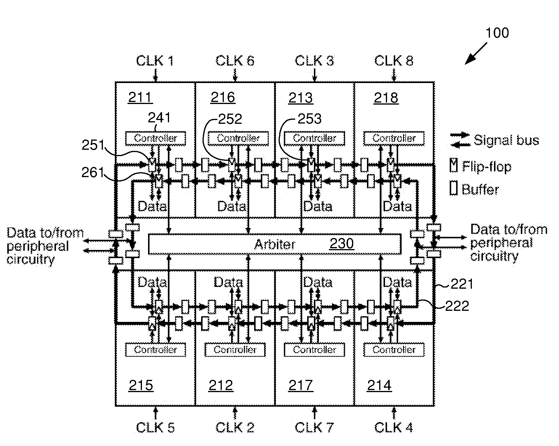
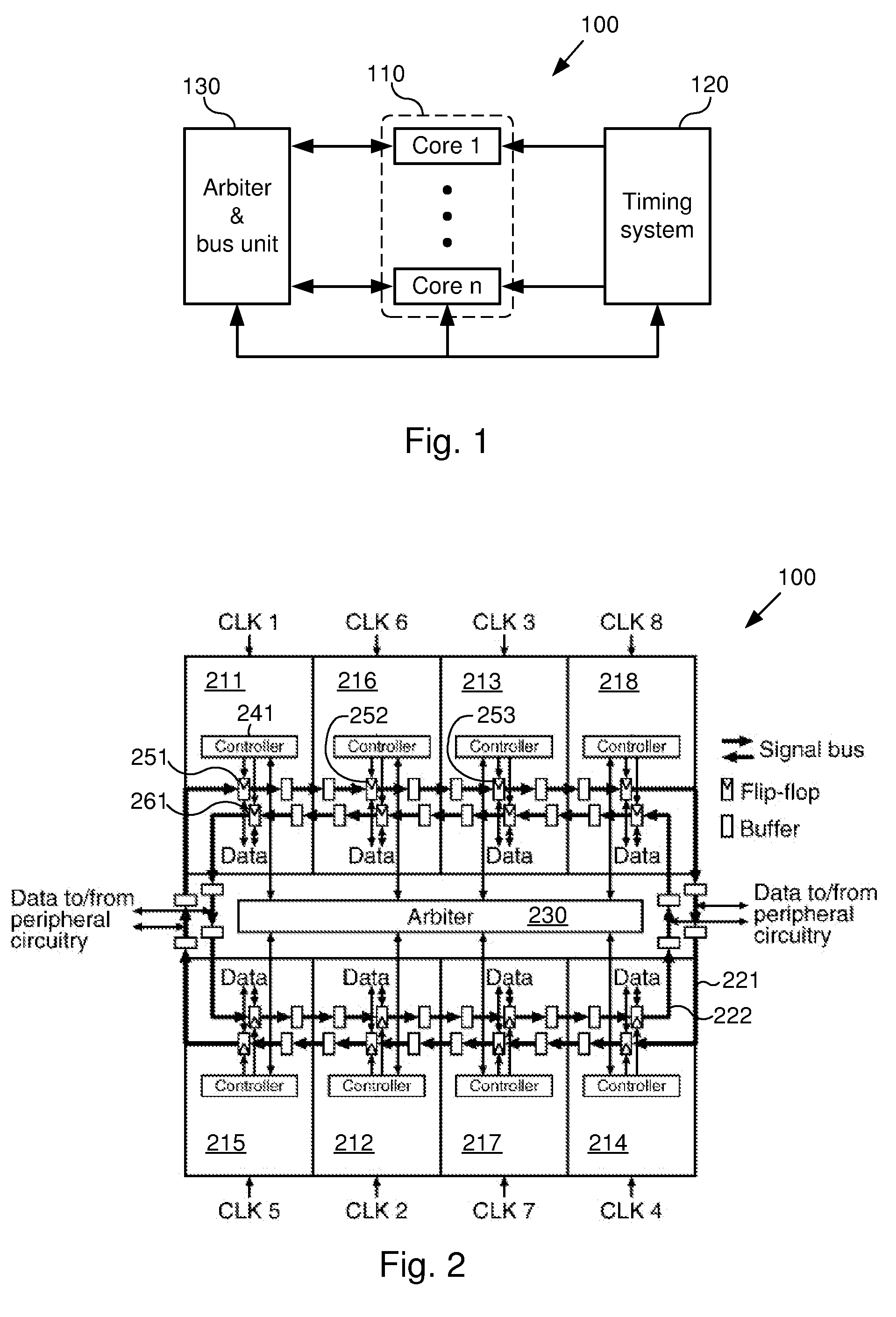
[0028]One embodiment comprises a multiprocessor system. The system includes multiple processor cores that are implemented on a single integrated circuit die. Each of the processor cores is coupled to a bus that enables the transfer of data and instructions to and from each of the processor cores. An arbiter is coupled to the bus and the processor cores to control the transfer of instructions and data over the bus.

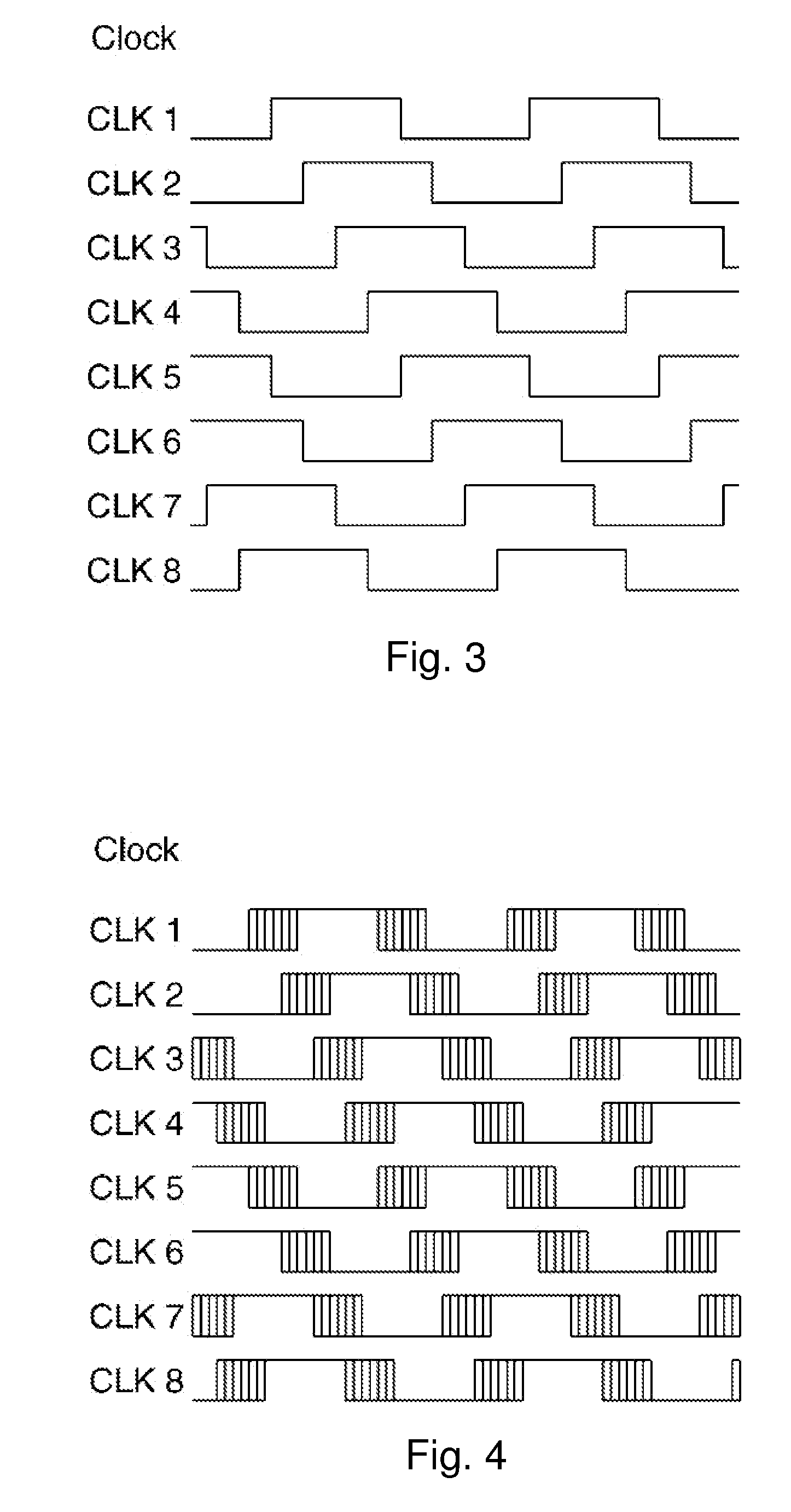
[0029]A timing system is coupled to each of the processor cores and to the arbiter. The timing system provides clock signals to each of these components of the system. The timing system...


PUM


Abstract

Systems and methods for transferring data using a ring bus architecture in a system that implements multi-phase clocking. In one embodiment, the system is a multiprocessor having multiple processor cores coupled to the ring bus. The bus may be a bidirectional bus having a first data path on which data is transferred in a clockwise direction and a second data path on which data is transferred in a counterclockwise direction. Controllers within the processor cores provide phase-shifted signals to the latches to clock data into them. Data transfers on the bus may be controlled by an arbiter which is coupled to the processor cores' controllers. The arbiter may schedule data transfers on the bus based on data transfer speeds associated with left-to-right and right-to-left data transfer directions. The arbiter may cause the phases of the clock signals to be selectively varied, or may cause the clock signals to be gated.

Description

BACKGROUND[0001]1. Field of the Invention[0002]The invention relates generally to systems and methods for transferring data in a multiprocessor system, and more particularly to systems and methods for transferring data using a ring bus architecture in a system that implements multiphase clocking.[0003]2. Related Art[0004]When integrated circuits such as processors are operated, they draw current from a power source. The logic components within an integrated circuit typically operate based on a clock signal, so the current drawn by the integrated circuit may suddenly increase at certain points in the clock cycle (e.g. at the rising edge of each clock cycle.) The high rate of change of the current (high di / dt) may cause electromagnetic interference (EMI) and / or noise in the power supply. Both EMI and power supply noise are undesirable.[0005]Reducing EMI and power supply noise is becoming more and more important in designing electronic systems. This is true for a number of reasons. For...

Claims


Application Information

Patent Timeline
IPC IPC(8): G06F1/10G06F13/14
CPCG06F13/364
Inventor YAMAOKA, HIROAKI
Owner TOSHIBA AMERICA ELECTRONICS COMPONENTS
Learn More