
System for simulating automated industrial plants

a technology for simulating industrial plants and industrial plants, applied in the direction of program control, total factory control, instruments, etc., can solve the problems of time-consuming and error-prone methods, and achieve the effects of reducing energy consumption, avoiding storage damage due to excessively long storage of short-lived intermediate products, and optimizing plant throughpu

Active Publication Date: 2009-10-22
SIEMENS AG +1
View PDF10 Cites 19 Cited by
  • Summary
  • Abstract
  • Description
  • Claims
  • Application Information

AI Technical Summary

Benefits of technology

[0013]An object of the invention is to reveal a way in which the simulation of the control programs of automated industrial plants can be more efficiently structured.
[0016]In this way the system detects potential congestion conditions in the material flow in the plant even before the start of production. In order to avoid such conditions and optimize the throughput of the plant the system optimizes the parameters of the controller in terms of the optimal size of buffers, the operating speeds of individual stations and machines, etc. Moreover, storage damage due to excessively long storage of short-lived intermediate products can be avoided by the optimization of the buffers.
[0017]In addition the plant and the individual machines and subplants can be operated with lower energy consumption and less wear and tear, since they run at their optimal speed.

Problems solved by technology

A problematic aspect of said prior art is that the simulation program (e.g. Plant Simulation) on the one hand and the PLC control program on the other hand create two worlds in terms of data, value type etc. between which no correlation exists.
Values determined by the simulation program must be input manually into the PLC control program, which in practice can prove a time-consuming and error-prone method.

Method used


Image

  • System for simulating automated industrial plants
  • System for simulating automated industrial plants
  • System for simulating automated industrial plants

Examples


Embodiment Construction

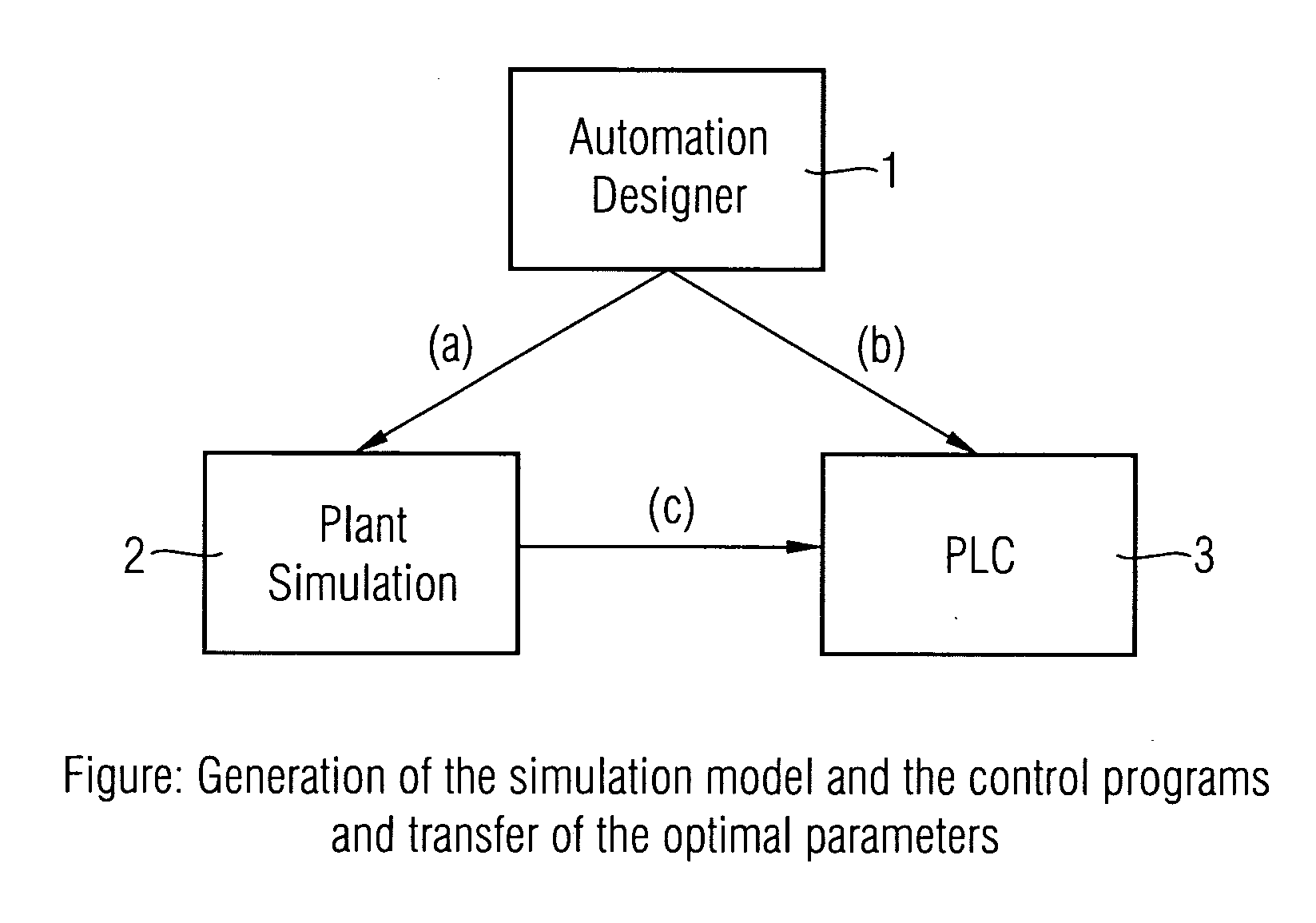
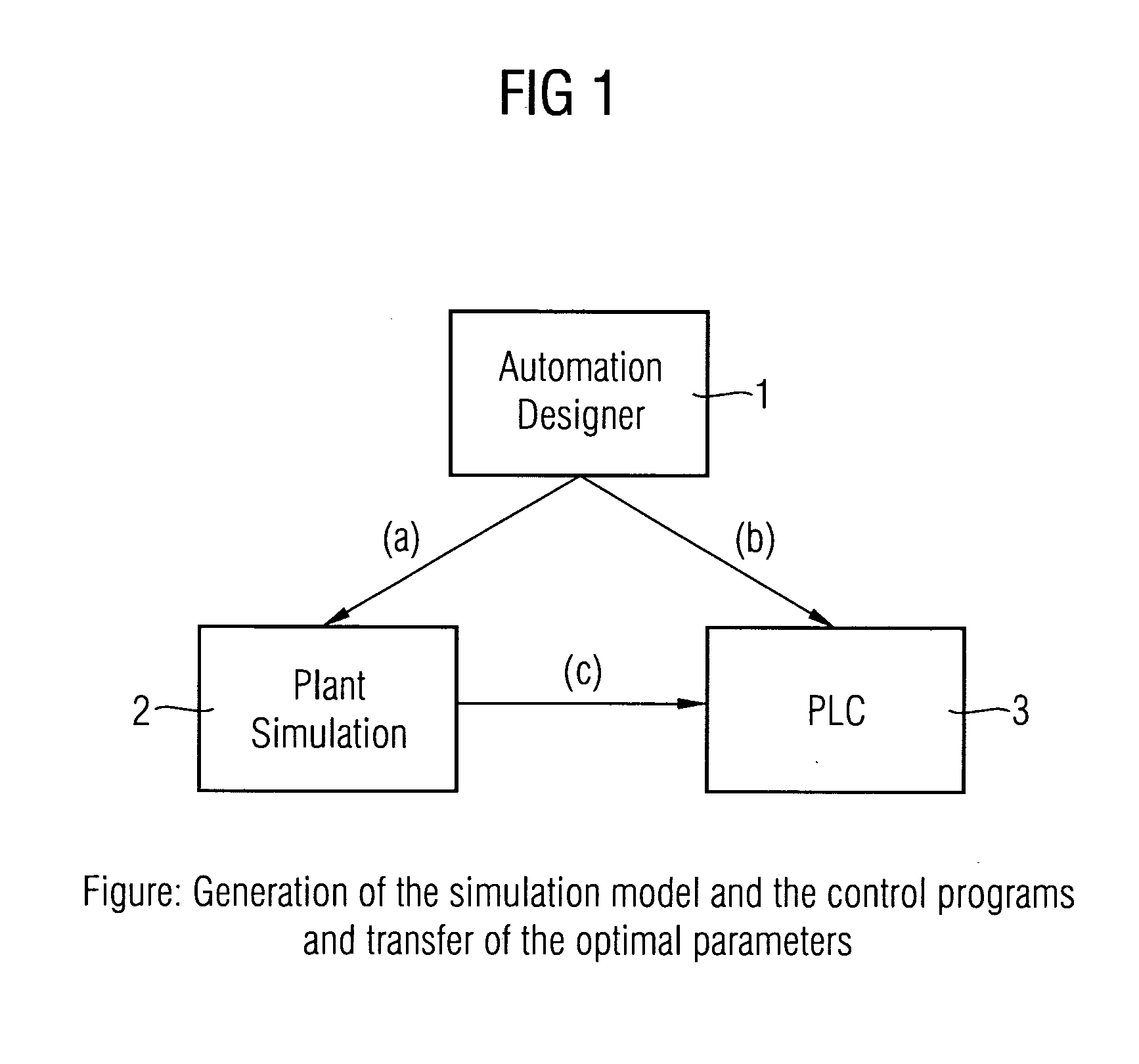
[0021]FIG. 1 shows the system consisting of a total of three components:

[0022]a high-level control program or engineering system (1),

[0023]the simulation system (2), and

[0024]the control program (3).

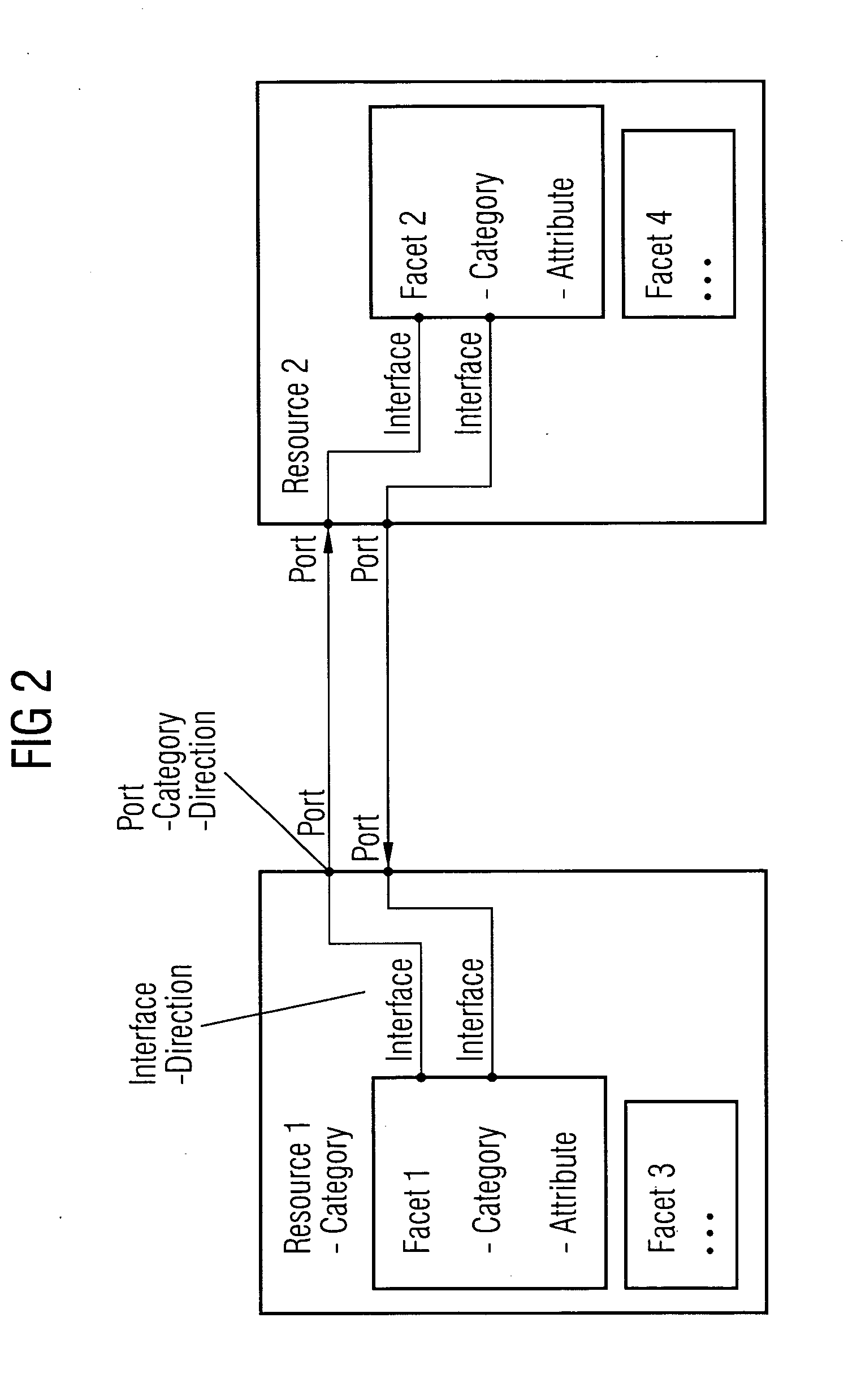
[0025]A model of the plant is stored in the high-level control program or engineering system (1). All the elements are mapped in the model by means of resources. A resource describes an element of an automated industrial plant. In addition, a resource has a plurality of facets which thus represent a fragment of a resource.

[0026]FIG. 2 shows the modeling of the data in detail. Thus, each component of the automation plant is assigned a resource object, each of said resource objects being assigned port data. The port data assigned to a resource object is created for each port of the resource object and identifies the data which can be exchanged via the respective port. An identification of said kind goes significantly beyond the pure definition of a valid data type, for it is intended to en...


PUM


Abstract

Automation technology facilities are used for automating industrial processes such as the control of conveyor belts. A high-level control device with a logical model of the plant stored in the control device is disclosed. Simulation models and control programs are generated by the control device. The generated control programs have special data blocks which contain the parameters that are to be optimized by the simulation. The generated simulation models generate the parameters as result values of the simulation evaluation algorithms and supply the values in an automated manner to the special data blocks of the generated control programs.

Description

CROSS REFERENCE TO RELATED APPLICATIONS[0001]This application claims priority of European Patent Application No. 08007536.9 EP filed Apr. 17, 2008, which is incorporated by reference herein in its entirety.FIELD OF INVENTION[0002]The invention relates to a system for simulating automated industrial plants.BACKGROUND OF INVENTION[0003]Automation technology facilities are used for automating industrial processes such as e.g. controlling machines or conveyor belts. Thus, for example, filling bottles or packaging foodstuffs calls for an automation plant whose components must be coordinated with one another to a particular degree. The bottles / foodstuffs are supplied via a conveyor belt to the plant and there are transported by way of a plurality of stations. The process material is brought to a stop and held in what are called buffers for filling / packaging purposes and subsequently transported onward via further conveyor belts.[0004]All components participating in the automated process a...

Claims


Application Information

Patent Timeline
Patent Type & Authority Applications(United States)
IPC IPC(8): G06F13/10G06F9/45
CPCG05B19/05G05B2219/23456G05B2219/13185Y02P90/02
Inventor PIEPENBROCK, GEORGSCHENK, BERNHARDSTOLPER, THILOZUHLSDORF, SOREN
Owner SIEMENS AG
Learn More