High-Pressure Discharge Lamp With Improved Ignitability and High-Voltage Pulse Generator

a discharge lamp and high-voltage pulse technology, which is applied in the direction of pulse generators, pulse techniques, lighting and heating apparatus, etc., can solve the problems of ineffective implementation, inconvenient design of feed lines, and high cost, and achieves compact design, high capacity of spiral pulse generators, and large temporal width of pulses.

Inactive Publication Date: 2009-10-22
OSRAM GMBH
View PDF16 Cites 1 Cited by
  • Summary
  • Abstract
  • Description
  • Claims
  • Application Information

AI Technical Summary

Benefits of technology

[0014]A very compact design is thus possible, which makes it possible to integrate the spiral pulse generator directly in the outer bulb of a lamp or in its base. The high pulse width also favors the flashover in the plasma of the discharge vessel.
[0022]high use temperature, with the result that the spiral pulse generator can be installed in the immediate vicinity of the lamp, in its base or even in its outer bulb;
[0032]In addition, a spiral pulse generator can be dimensioned such that the high-voltage pulse even allows for hot-restarting of the lamp. The dielectric made from ceramic is characterized by an extremely high dielectric constant εr in the range of εr>10, with it being possible for an ε of typically ε=70 to 100 to be achieved depending on the material and construction. This allows for a very high capacity of the spiral pulse generator and allows for a comparatively large temporal width of the pulses generated. As a result, a very compact design of the spiral pulse generator is possible, with the result that it can be integrated in conventional outer bulbs of high-pressure discharge lamps.
[0033]The high pulse width also facilitates the flashover in the discharge volume.

Problems solved by technology

One disadvantage with this is the fact that the feed lines need to be designed to be resistant to high voltages.
However, they could not be implemented because, for one reason, they are too expensive.
Secondly, the advantage of integrating them in the base is insufficient since the problem of supplying the high voltage into the bulb remains.
The probability of damage to the lamp, whether it be insulation problems or a rupture in the base, therefore increases considerably.

Method used


Image

  • High-Pressure Discharge Lamp With Improved Ignitability and High-Voltage Pulse Generator
  • High-Pressure Discharge Lamp With Improved Ignitability and High-Voltage Pulse Generator
  • High-Pressure Discharge Lamp With Improved Ignitability and High-Voltage Pulse Generator

Examples


Embodiment Construction

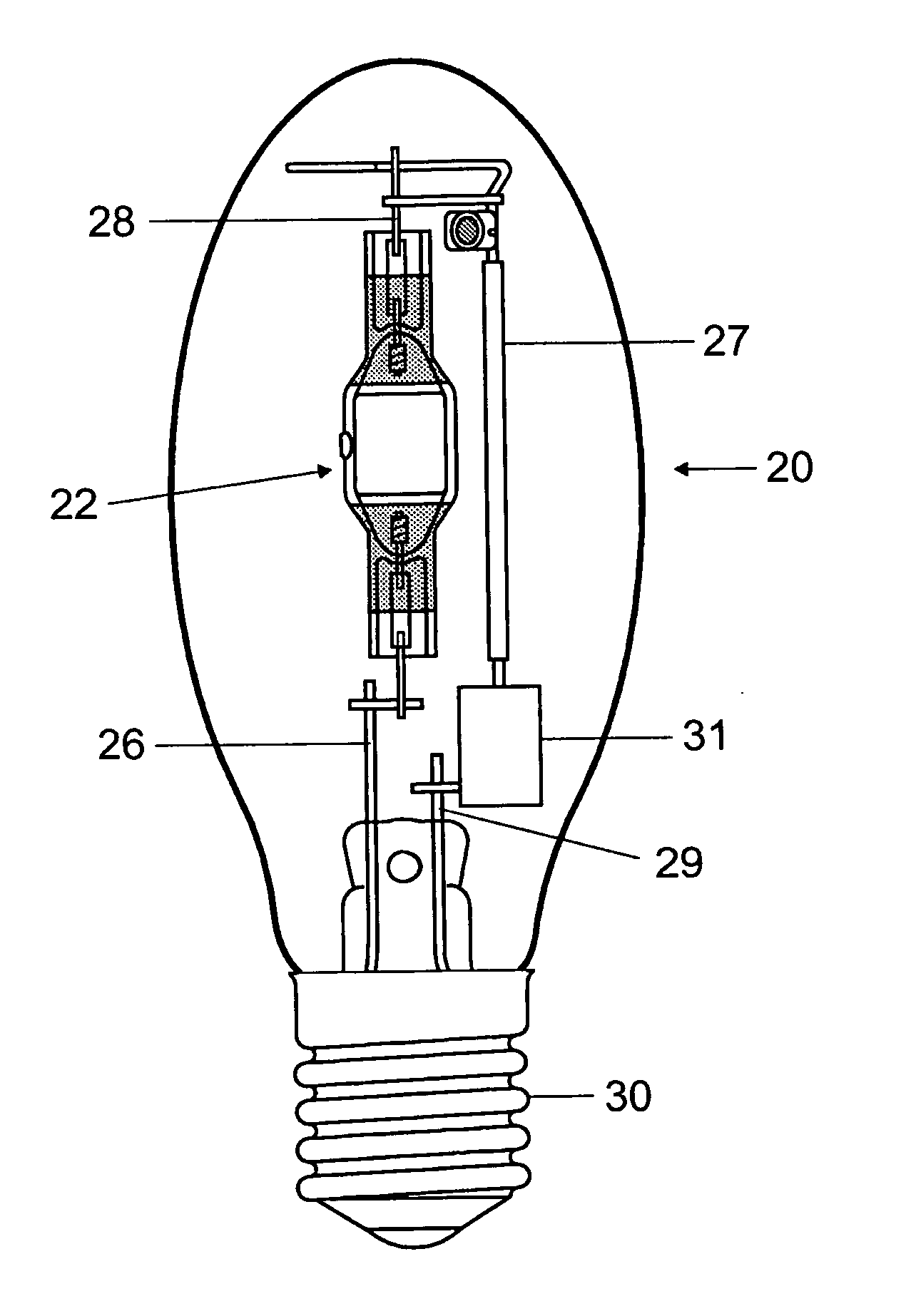
[0004]The object of the present invention is to provide a high-pressure discharge lamp whose ignition response is markedly improved in comparison with previous lamps and with which there is no danger of any damage as a result of the high voltage. This applies in particular to metal-halide lamps, with it being possible for the material of the discharge vessel to either be quartz glass or ceramic.

[0005]This object is achieved by the characterizing features of claim 1.

[0006]Particularly advantageous configurations are given in the dependent claims.

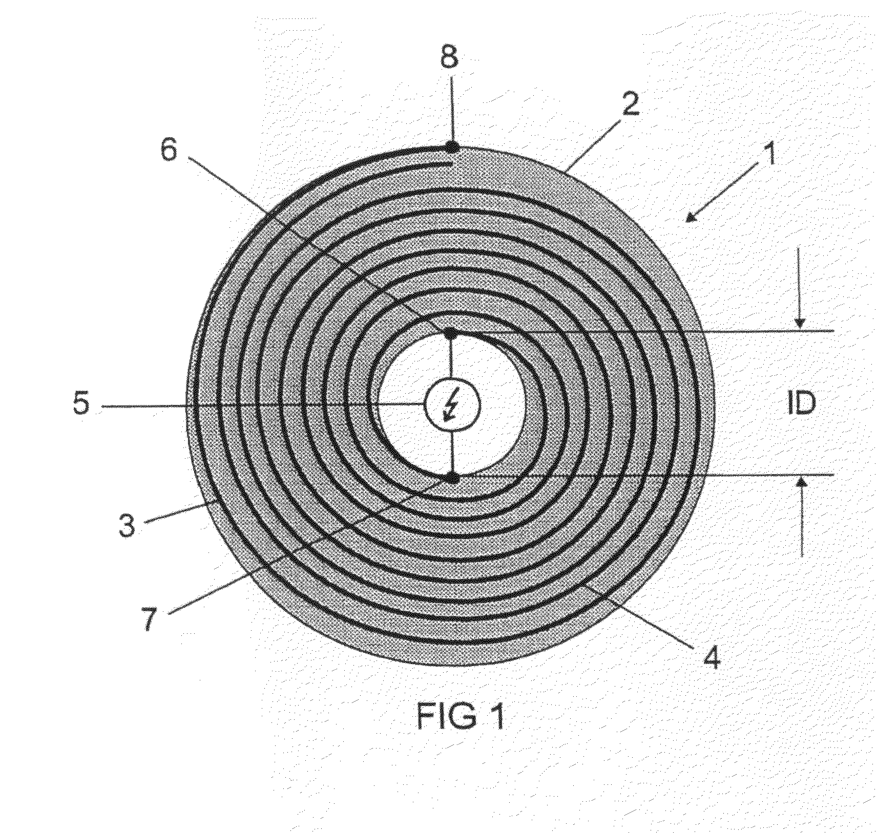
[0007]Furthermore, an object of the present invention is to specify a compact high-voltage pulse generator. This object is achieved by the characterizing features of claim 14.

[0008]According to the invention, a high-voltage pulse with at least 1.5 kV, which is required for igniting the lamp, is now generated by means of a special temperature-resistant spiral pulse generator, which is integrated in the immediate vicinity of the discharge vesse...


PUM


Abstract

High pressure discharge lamp (20) with improved ignitability. A spiral pulse generator (1) that is directly mounted inside the outer piston (12) of the lamp is used for igniting the high pressure discharge lamp.

Description

TECHNICAL FIELD[0001]The invention is based on a high-pressure discharge lamp in accordance with the preamble of claim 1. Such lamps are in particular high-pressure discharge lamps for general lighting or for photooptical purposes or for motor vehicle lighting. The invention furthermore relates to a high-voltage pulse generator which can be used in particular for a lamp.PRIOR ART[0002]The problem associated with the ignition of high-pressure discharge lamps is at present solved by virtue of the fact that the ignition device is integrated in the ballast. One disadvantage with this is the fact that the feed lines need to be designed to be resistant to high voltages.[0003]In the past, repeated attempts have been made to integrate the ignition unit in the lamp. These attempts involve integrating it in the base. Particularly effective ignition which promises high pulses is achieved by means of so-called spiral pulse generators; see U.S. Pat. No. 3,289,015. Quite some time ago such device...

Claims


Application Information

Patent Timeline
Patent Type & Authority Applications(United States)
IPC IPC(8): H01J61/54F21Y101/00
CPCH01F27/323H01F41/0604H01J61/34H05B41/042H01J61/56H03K3/537H01J61/547H01F41/061H01J5/54H01J61/827
Inventor KLOSS, ANDREASLIEPOLD, UTESCHUH, CARSTENSTEINKOPFF, THORSTENSTOCKWALD, KLAUSWALTER, STEFFEN
Owner OSRAM GMBH
Why Eureka
Try Eureka