
Compact, thermally stable fiber-optic array mountable to flow cell

a technology of optical fiber arrays and flow cells, applied in the field of optical systems, can solve the problems of measurement errors, drawbacks of existing flow cell fluorescent analysis systems,

Active Publication Date: 2009-10-15
IDEX HEALTH & SCI +1
View PDF59 Cites 21 Cited by
  • Summary
  • Abstract
  • Description
  • Claims
  • Application Information

AI Technical Summary

Benefits of technology

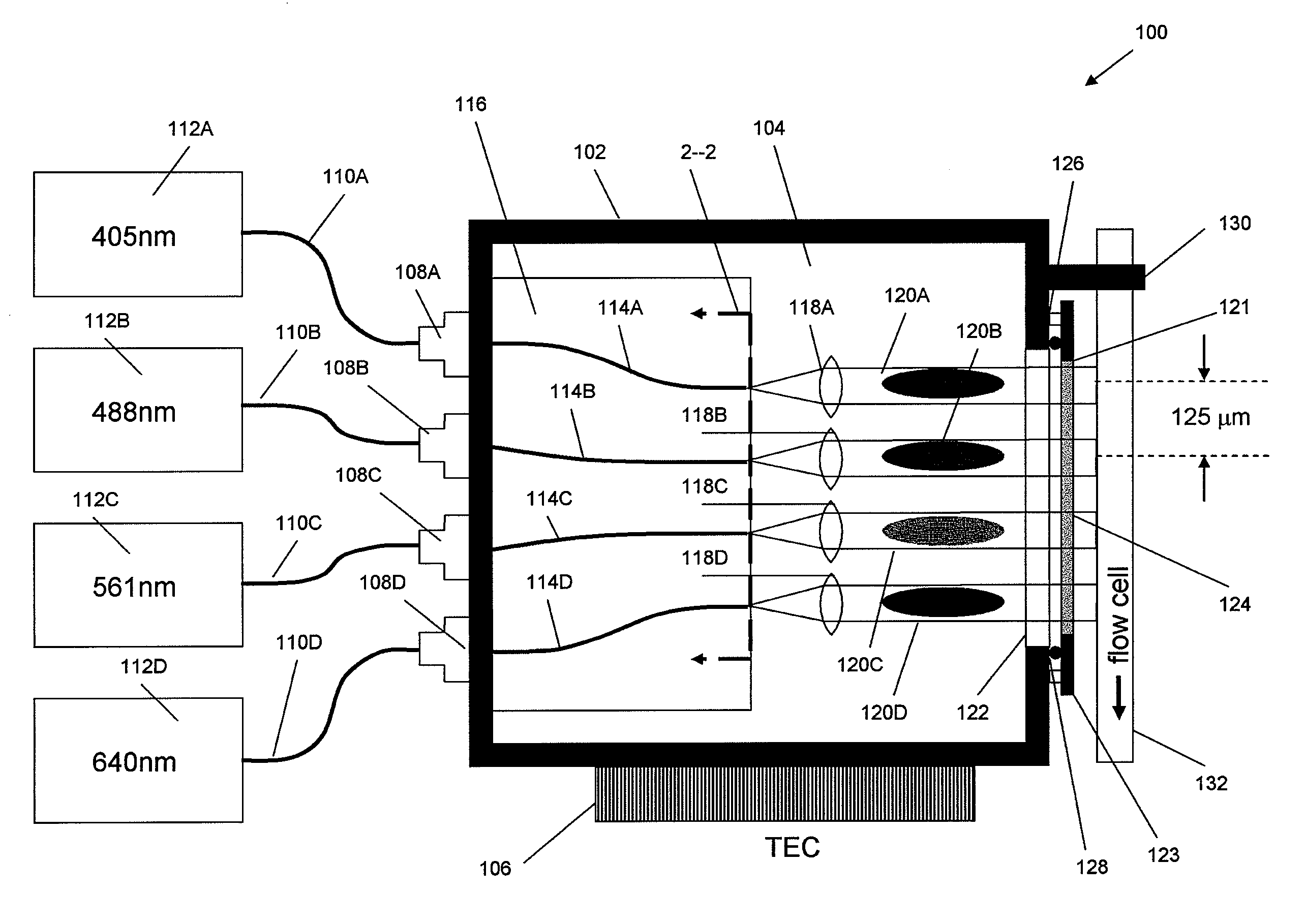
[0007]Various embodiments described herein provide the ability to perform optical measurements on flow cells while addressing some of the drawbacks encountered with conventional approaches, such as temperature instability and the resultant pointing errors and signal power fluctuations. A wide range of embodiments, however, are disclosed.
[0008]Various embodiments disclosed herein, for example, comprise a laser system for directing light for optical measurements, such as laser-induced fluorescence. The laser system can include a thermally conductive housing defining an interior chamber, and a thermoelectric controller thermally coupled to the housing. The laser system can include a plurality of optical input ports, and the op

Problems solved by technology

Existing systems for fluorescent analysis of flow cells, however, suffer from various drawbacks, such as measurement error.

Method used


Image

  • Compact, thermally stable fiber-optic array mountable to flow cell
  • Compact, thermally stable fiber-optic array mountable to flow cell
  • Compact, thermally stable fiber-optic array mountable to flow cell

Examples


Embodiment Construction

[0026]Embodiments of the inventions will now be described with reference to the accompanying figures. Although certain preferred embodiments and examples are disclosed herein, inventive subject matter extends beyond the specifically disclosed embodiments to other alternative embodiments and / or uses of the inventions, and to modifications and equivalents thereof. Thus, the scope of the inventions herein disclosed is not limited by any of the particular embodiments described below. For example, in any method or process disclosed herein, the acts or operations of the method or process may be performed in any suitable sequence and are not necessarily limited to any particular disclosed sequence.

[0027]For purposes of contrasting various embodiments with the prior art, certain aspects and advantages of these embodiments are described. Not necessarily all such aspects or advantages are achieved by any particular embodiment. Thus, for example, various embodiments may be carried out in a man...


PUM


Abstract

Various embodiments of an optical system for directing light for optical measurements such laser-induced fluorescence and spectroscopic analysis are disclosed. In some embodiments, the optical system includes a thermally conductive housing and a thermoelectric controller, a plurality of optical fibers, and one or more optical elements to direct light emitted by the optical fibers to illuminate a flow cell. The housing is configured to attach to a flow cell.

Description

CROSS-REFERENCE TO RELATED APPLICATIONS[0001]This application claims the benefit of U.S. Provisional Application No. 61 / 042,640, filed Apr. 4, 2008, which is incorporated by reference in its entirety.BACKGROUND OF THE INVENTION[0002]1. Field of the Invention[0003]This disclosure relates generally to optical systems for directing light to a sample contained in a flow cell, and more particularly to a compact, thermally stable, optical fiber array attachable to a flow cell for directing laser light to the flow cell for optical measurements such as laser-induced fluorescence.[0004]2. Description of the Related Art[0005]Optical analysis of flow cells, such as laser-induced fluorescence, involves illuminating biological samples with laser light in order to test samples which may, for example, be tagged with fluorescent dyes. Fluorescent dyes absorb light at certain wavelengths and in turn emit their fluorescence energy at a different wavelength. This emission can be detected to ascertain ...

Claims


Application Information

Patent Timeline
IPC IPC(8): G01N1/10G01J1/58
CPCG01J3/0286G01J3/10G01N21/05G01N2021/0346G01N21/6402G01N21/645G01N2021/6419G01N21/31
Inventor HARGIS, DAVID E.
Owner IDEX HEALTH & SCI
Learn More