
Pneumatic tire for motorcycle

a technology for pneumatic tires and motorcycles, applied in the direction of non-skid devices, cycles, transportation and packaging, etc., can solve the problems of reducing the stiffness of the block, increasing the deformation volume of the block, and reducing the grip force, so as to improve the turning performan

Active Publication Date: 2009-10-15
BRIDGESTONE CORP
View PDF5 Cites 15 Cited by
  • Summary
  • Abstract
  • Description
  • Claims
  • Application Information

AI Technical Summary

Benefits of technology

[0012]The present invention aims to overcome the above-mentioned problems and to provide a pneumatic tire for a motorcycle capable of improving turning performance on a wet road surface as compared to that of conventional tires.

Problems solved by technology

Therefore, it is considered that a thin groove having a width of about 1.0 mm, which is referred to as a sipe, is not suitable for draining water and that forming this sipe on the tread portion is nothing more than cutting a land portion of the tread portion, which results in reducing block stiffness, increasing deformation volume of the block and reducing a grip force.

Method used


Image

  • Pneumatic tire for motorcycle
  • Pneumatic tire for motorcycle
  • Pneumatic tire for motorcycle

Examples


first embodiment

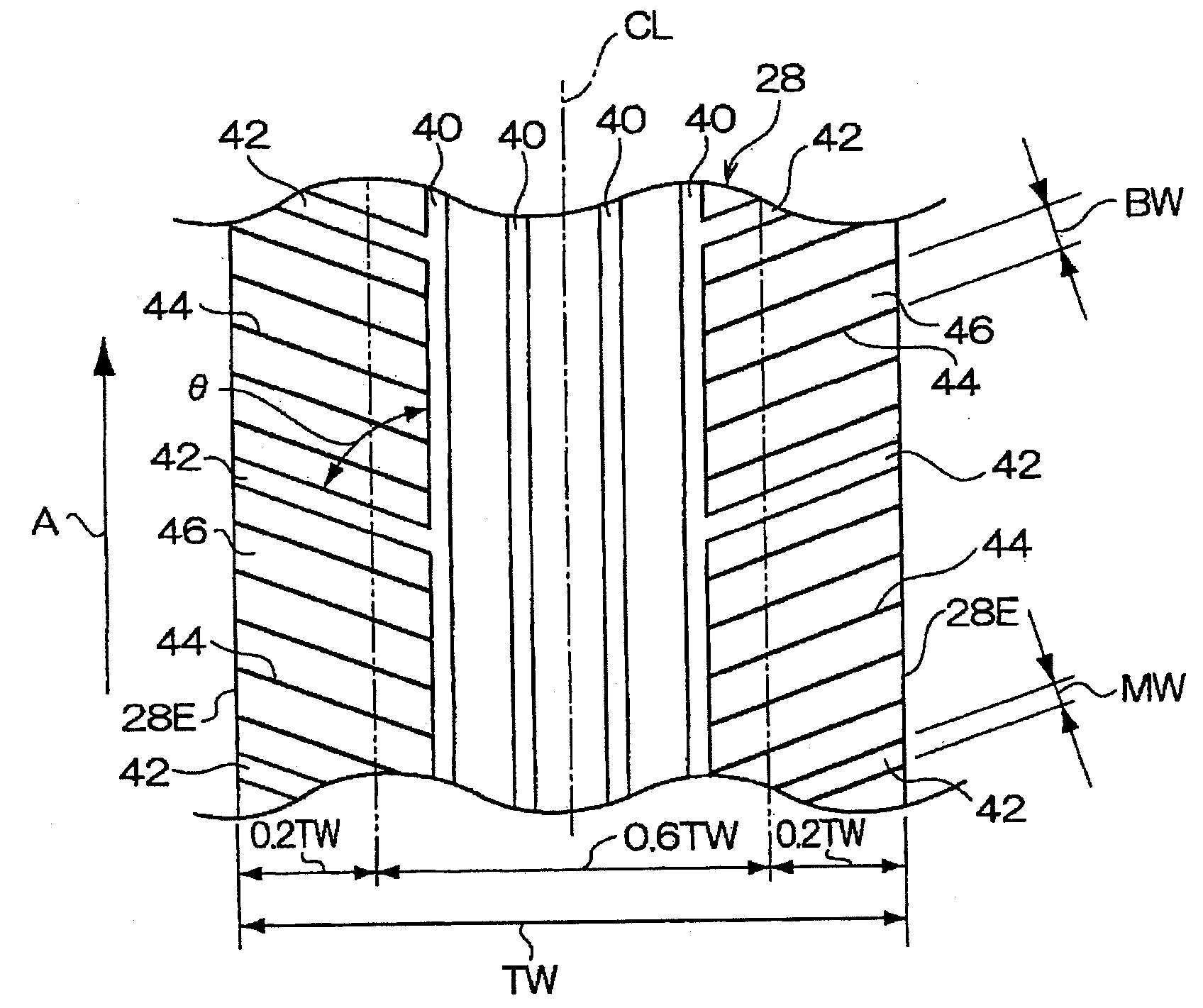
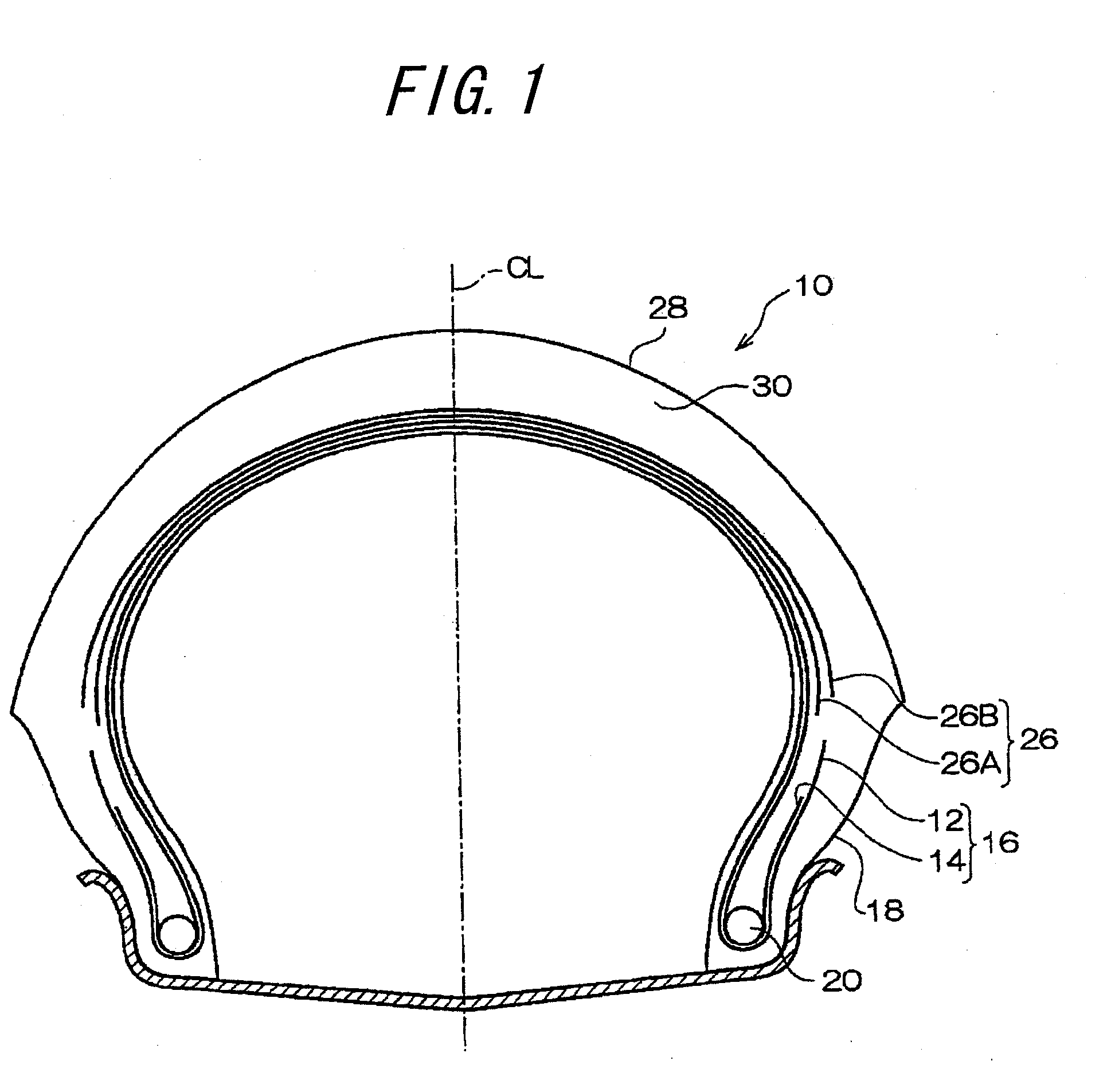
[0090]A first embodiment of a pneumatic tire for a motorcycle of the present invention will be described with reference to FIGS. 1 and 2.

[0091](Carcass)

[0092]As a sectional view along an axis of rotation of a tire is shown in FIG. 1, a pneumatic tire 10 for a motorcycle of this embodiment has a carcass 16 consisting of a first carcass ply 12, in which cords extending in the inclined direction with respect to a tire equatorial plane CL are embedded and a second carcass ply 14, in which cords extending in the opposite inclined direction of said cords with respect to the tire equatorial plane CL.

[0093]The tire 10 for a motorcycle of this embodiment is used for a front wheel and has a tire size of 120 / 60R17.

[0094]Both ends of the first carcass ply 12 and the second carcass ply 14 are turned around bead cores 20, which are embedded in bead portions 18, from the inner to outer sides of the tire.

[0095]The first carcass ply 12 is formed by arranging a plurality of cords (for example, organi...

example tire 1

[0130]Example tire 1 is a tire of the above-mentioned first embodiment, having a pattern shown in FIG. 2.

example tire 2

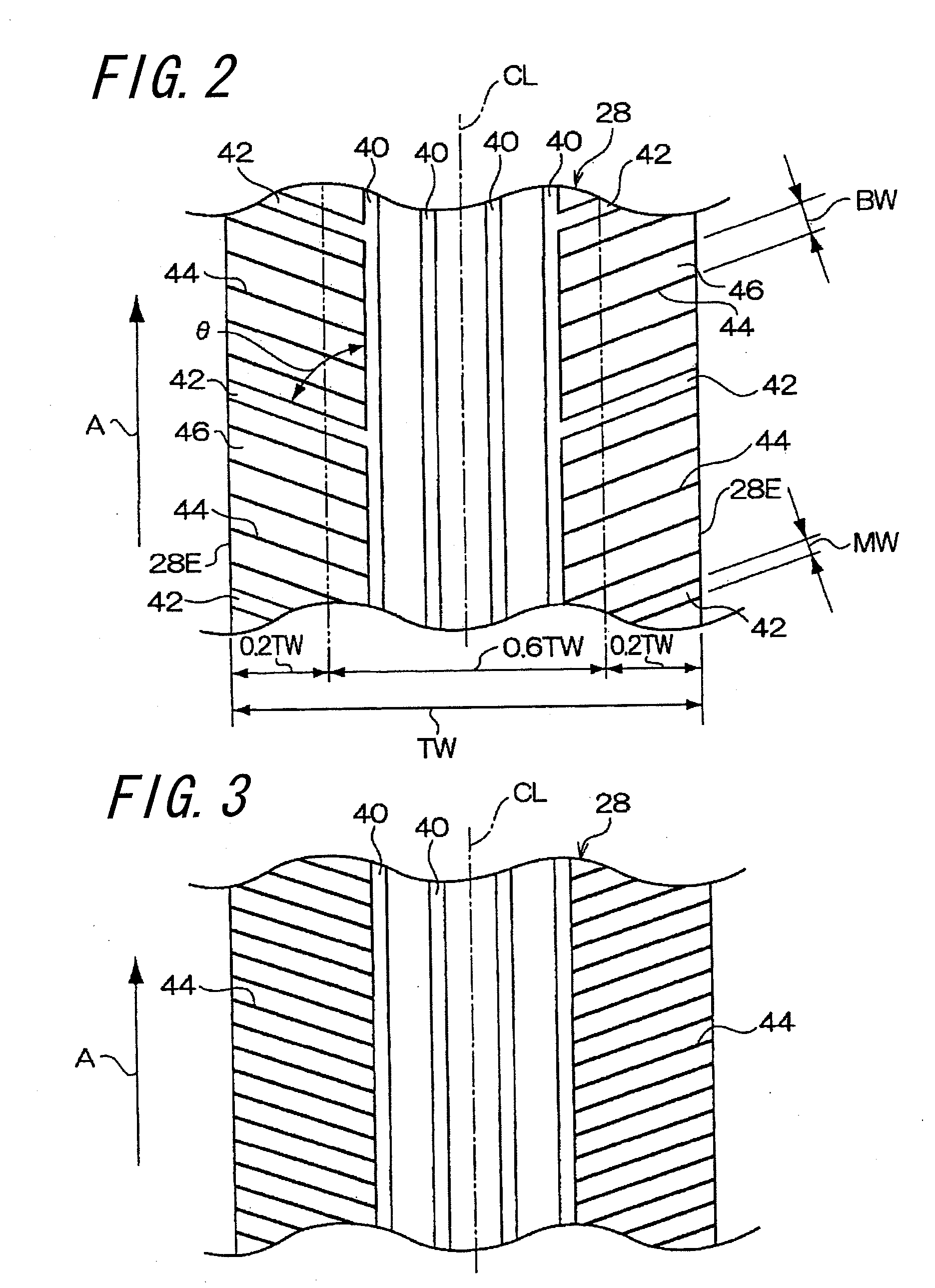
[0131]Example tire 2 has a pattern shown in FIG. 3, in which no wide inclined grooves having a groove width of not less than 2.5 mm are not provided in the tread side portions. All grooves provided in the pattern side portions are narrow inclined grooves having a width of 1 mm and elongated land portions separated by these narrow inclined grooves have a width of 8 mm. Except for the above-mentioned points, Example tire 2 has the same configuration of that of Example tire 1.


PUM


Abstract

The present invention aims to provide a pneumatic tire for a motorcycle capable of improving turning performance on a wet road surface as compared to that of conventional tires. The pneumatic tire for a motorcycle comprises a tread 28 consisting of a tread central portion having a width of 60% of a tread developed width and tread side portions located outside of the tread central portion in the width direction of the tire and a plurality of wide inclined grooves 42 and narrow inclined grooves 44 inclined at an angle of less than 90 degrees with respect to the circumferential direction of the tire formed in the tread side portion such that the grooves continuously extend over a region of 50% or more of a width of the tread side portion. A groove width of the narrow inclined grooves 44 is set within a range between 0.3 mm and 2.5 mm. A total area of the wide inclined grooves 42 is set to not more than 20% of an area of the tread side portion. Such configuration can satisfy both of drainage performance and block stiffness of the tread contact portion in turning at a high level to obtain a higher grip force in turning on a wet road surface than that of conventional tires.

Description

TECHNICAL FIELD[0001]The present invention relates to a pneumatic tire for a motorcycle and particularly relates to a pneumatic tire for a motorcycle capable of improving turning performance on a wet road surface.RELATED ART[0002]A tire is provided with grooves on its tread portion to enable rubber of the tread surface to obtain an excellent contact state free of a water film during traveling on a wet road surface (refer to JP-2003-211917A, for example). That is, the grooves provided on the tread portion serve as escape routes of water squeezed by the tread and the road surface so as to efficiently drain such water.[0003]Regarding a tread pattern for a motorcycle, designing a groove arrangement is technically difficult and is a key factor in determining wet performance. Therefore, a tread pattern is designed to ensure a good balance between a groove arrangement capable of efficient water drainage and good appearance in design.[0004]A motorcycle turns a corner with its vehicle body b...

Claims


Application Information

Patent Timeline
IPC IPC(8): B60C11/04B60C11/03
CPCB60C11/0302B60C11/0306B60C2011/0374B60C2011/0313B60C2011/0341B60C2200/10
Inventor ISHIYAMA, MAKOTOMATSUMOTO, HIROYUKIKATAYAMA, SHINSAKU
Owner BRIDGESTONE CORP
Learn More