
Servo position/stress detection control system

a technology of position/stress detection and control system, which is applied in the direction of programme control, dynamo-electric converter control, instruments, etc., can solve the problems of inability to meet the precision degree achieved by machine operation, the design of the optical scale cannot achieve a zero degree angle between the gratings of the first and second graduated scales optical scale, and the difficulty of detecting devices, etc., to achieve high precision

Active Publication Date: 2009-10-15
WANG WEN LIANG
View PDF7 Cites 4 Cited by
  • Summary
  • Abstract
  • Description
  • Claims
  • Application Information

AI Technical Summary

Benefits of technology

[0010]The main objective of the invention is to provide a servo position / stress detection control system that provides position and / or stress control of high precision.
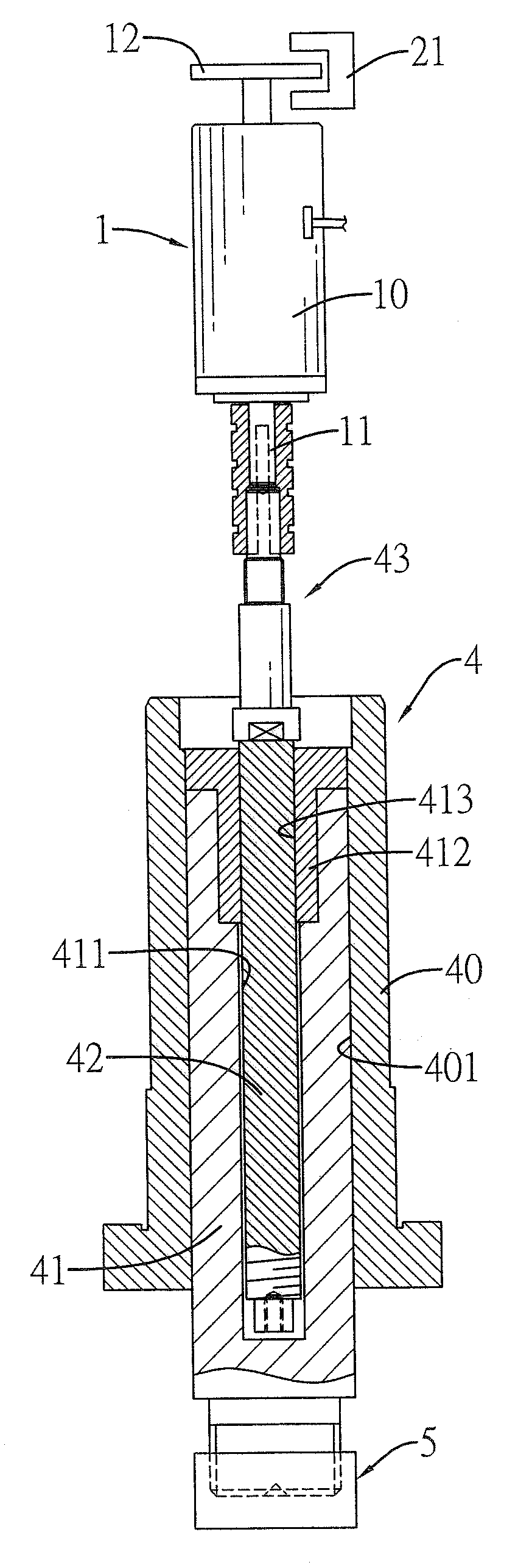
[0014]With foregoing system, the control unit of the servo driver drives the servomotor with electricity, the servomotor then pushes the driving shaft moving downward and pressing the workpiece. The operating unit of the controller accesses the feedback torque value from the servomotor to obtain the height and force value of the driving shaft. The servo driver then adjust the pressure exerted on the workpiece according to the load line to exclude possible errors caused by the stress and variance of height of the driving shaft to truly reflect exact pressure and position and then enhance the machining precision of workpiece.

Problems solved by technology

However, design of the optical scale can hardly achieve a zero degree angle between gratings of the first and second graduated scales optical scale.
Therefore during light transmission and signal amplification, precision degree achieved by the machine operation still do not meet requirements.
However the force detecting device may be easily affected by mechanical equipment and cannot actually and precisely measure the force exerting on workpiece.
Therefore precision of machine operation still do not meet requirements.
Only when the linear shifting device exerting different pressure on workpiece using a press member, press member or workpiece being pressed may have variance of height due to reacting forces and cause the output force and device position cannot be actually reflected and cannot achieve great precision of position.

Method used


Image

  • Servo position/stress detection control system
  • Servo position/stress detection control system
  • Servo position/stress detection control system

Examples


Embodiment Construction

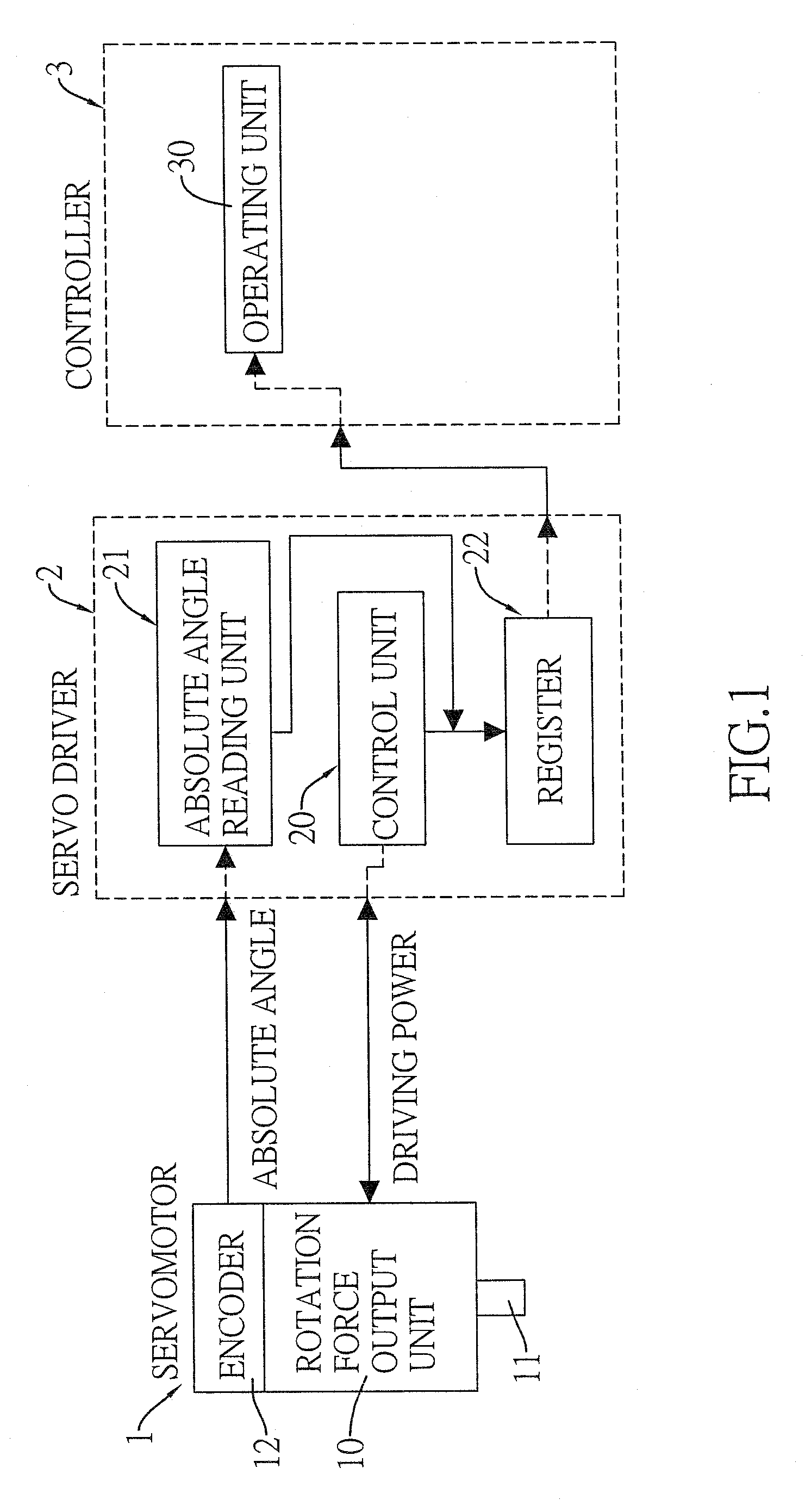
[0027]The present invention may comprise a servo position detection control system and a servo stress detection system. With reference to FIGS. 1 and 2, a servo position detection control system in accordance with the present invention comprises a servomotor (1), a servo driver (2) and a controller (3). The servo driver (2) and the controller (3) may further integrated into a control device or a computer.

[0028]The servomotor (1) is a controllable device that outputs rotation force. The servomotor (1) has a rotation force output unit (10) and an encoder (12). The rotation force output unit (10) has a spindle (11). The encoder (12) is connected to the spindle (11) and rotates with the spindle (11).

[0029]The servo driver (2) has a control unit (20), an absolute angle reading unit (21) and a register (22). The control unit (20) is connected to the servomotor (1) via a power-connecting interface and selectively drives or stops the servomotor (1). The absolute angle reading unit (21) is m...


PUM

PropertyMeasurementUnit
zero degree angleaaaaaaaaaa
rotation forceaaaaaaaaaa
absolute angleaaaaaaaaaa

Abstract

A servo position / stress detection control system has a servomotor, a servo driver and a controller. The servo driver has a control unit, an absolute angle reading unit and a register. The control unit selectively drives or stops the servomotor and converts torque value of the servomotor to a force value. The absolute angle reading unit reads an absolute angle value of rotation in response to a spindle of the servomotor. The controller respectively converts the absolute angle value and the force value to a linear displacement and a load stress value with a calculating program, establishes a load line in response to different force values and corresponding linear displacements wherein the load line provides corresponding correction basis for the servo driver to automatically detect height variances caused by reacting force and accordingly adjust working status of the servomotor.

Description

BACKGROUND OF THE INVENTION[0001]1. Field of the Invention[0002]The present invention relates to a servo detection control system, especially to a servo position / stress detection control system that provides position and / or stress control of high precision.[0003]2. Description of the Related Art[0004]Driving mechanism of a conventional precision machine may be combined with displacement or force detecting devices for making the precision machine meet the requirement of expected precision.[0005]Foregoing displacement detecting device may be a linear optical scale wherein the optical scale applies moire method by making lights pass through condensing lens, a first graduated scale, a second graduated scale and a light detector to bring moire fringe effect on the light detector. Light signal may be amplified and be converted into a displacement signal and send back to a control device of the precision machine for measurement.[0006]The displacement detecting device using linear optical s...

Claims


Application Information

Patent Timeline
Patent Type & Authority Applications(United States)
IPC IPC(8): G01L1/00H02P8/00H02P29/00
CPCG05B2219/41056G05B19/404
Inventor WANG, WEN-LIANG
Owner WANG WEN LIANG
Learn More