
Sodium ion based aqueous electrolyte electrochemical secondary energy storage device

Inactive Publication Date: 2009-10-08
CARNEGIE MELLON UNIV
View PDF58 Cites 145 Cited by
  • Summary
  • Abstract
  • Description
  • Claims
  • Application Information

AI Technical Summary

Benefits of technology

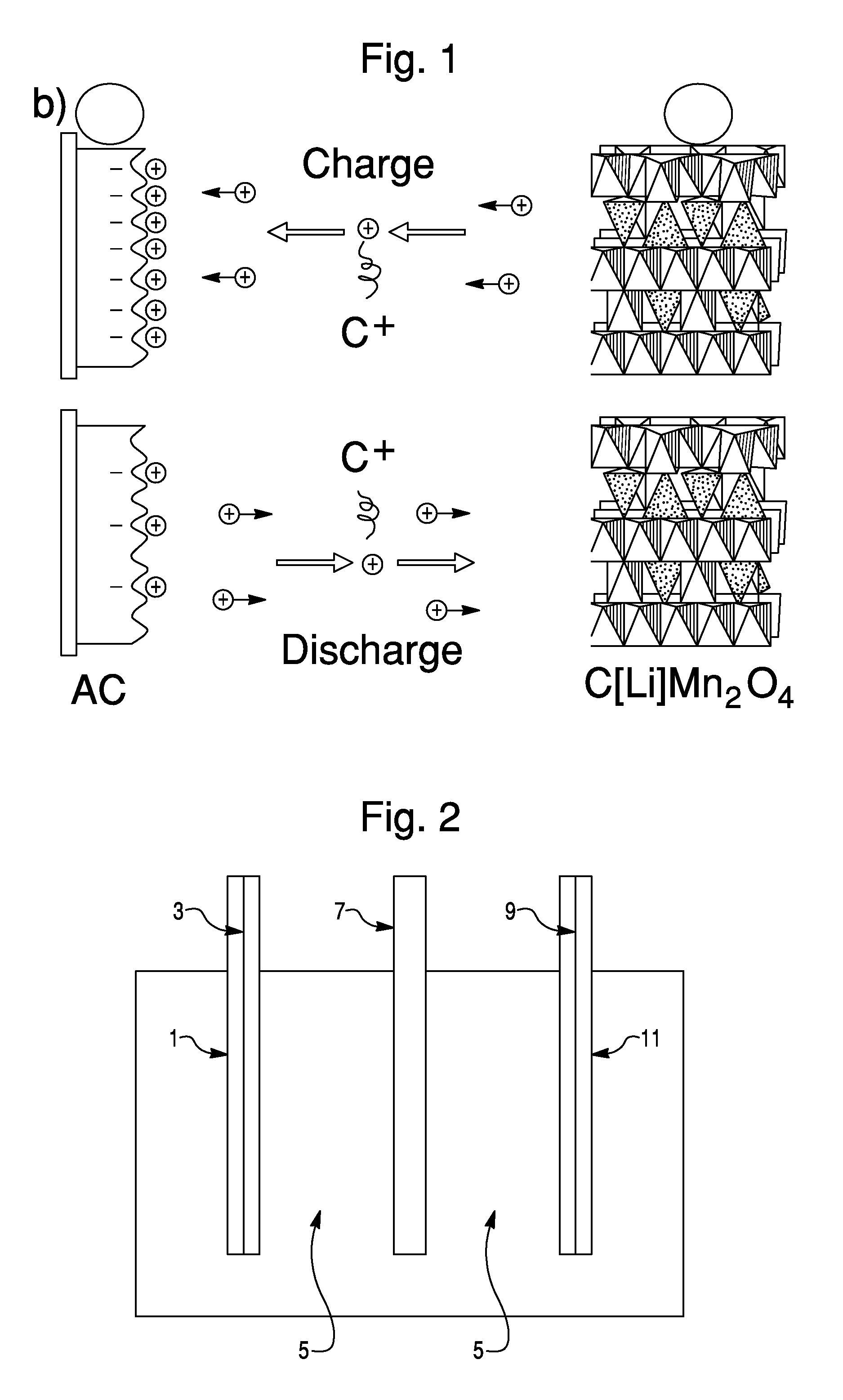
[0008]As used herein, the term faradaic reaction indicates a reaction that results in oxidation or reduction of an involved species. For example, in embodiments of the present invention, when Na cations intercalate in to active cathode materials, the active cathode materials must be reduced (that is

Problems solved by technology

While these cells function well enough to support this application, there are a number of problems associated with their use, including: heavy use of environmentally unclean lead and acids (it is estimated that the Pb-acid technology is responsible for the release of over 100,000 tons of Pb into the environment each year in the US alone), significant degradation of performance if held at intermediate state of charge or routinely cycled to deep levels of discharge, a need for routine servicing to maintain performance, and the implementation of a requisite recycling program.
Unfortunately the economics of alternative battery chemistries has made this a very unappealing option to date.

Method used


Image

  • Sodium ion based aqueous electrolyte electrochemical secondary energy storage device
  • Sodium ion based aqueous electrolyte electrochemical secondary energy storage device
  • Sodium ion based aqueous electrolyte electrochemical secondary energy storage device

Examples


example 1

[0090]A test cell was constructed with a λ-MO2-type active cathode material versus an activated carbon anode material in 1 M Na2SO4 in DI H2O electrolyte.

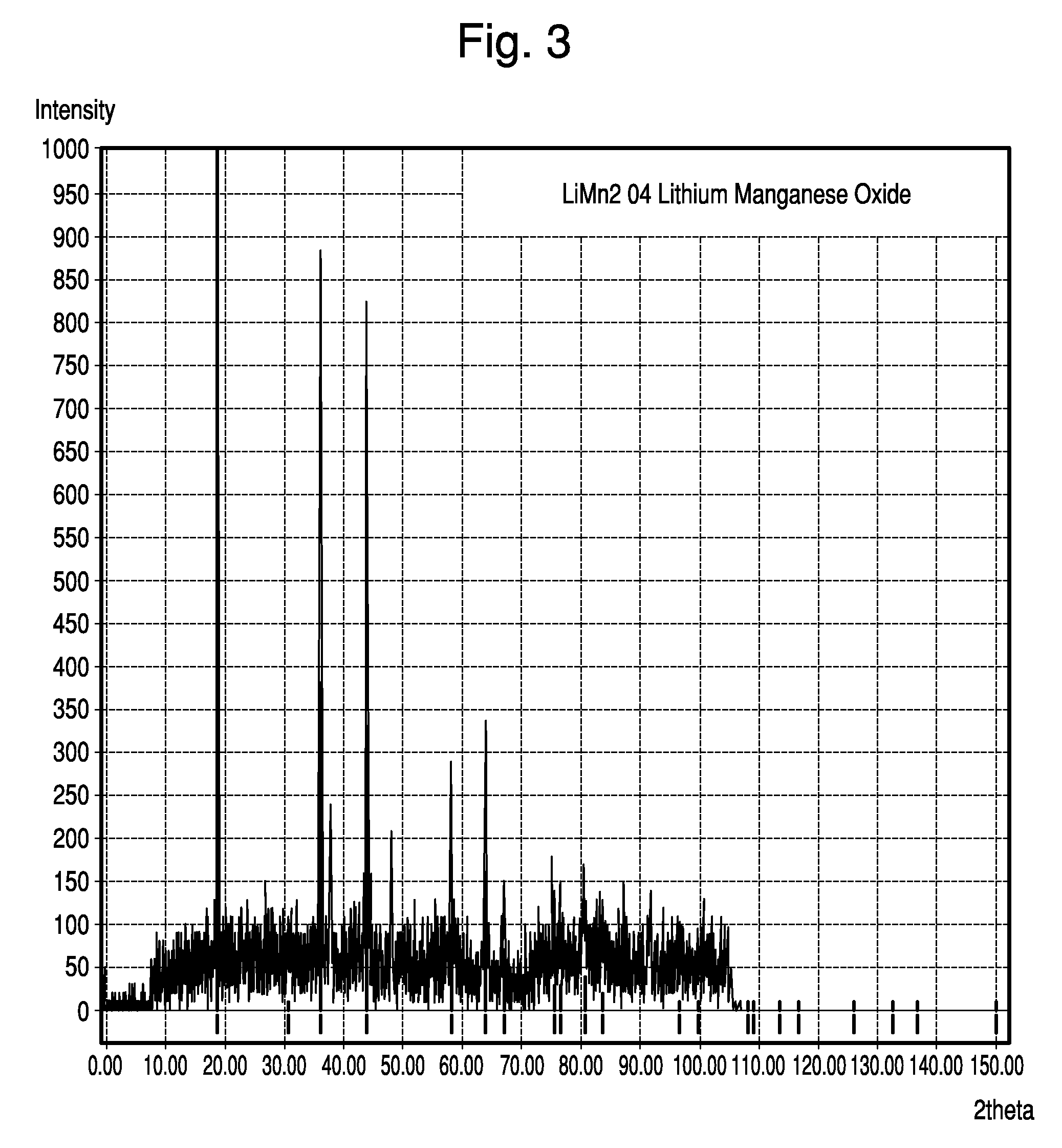
[0091]The active cathode material was made from Al-doped, Li-containing, cubic spinel MnO2. Specifically, the Li-containing cubic spinel was synthesized by thoroughly mixing Li2CO3, Mn2O3, and Al(OH)3 to proper mole ratios and firing at 750° C. for 24 hours. This material resulted in a spinel structure with the formula Li1.05Mn1.89Al0.06O4, as verified by X-ray diffraction analysis. X-ray spectra is shown in FIG. 3. As the X-ray data confirm, this material fits the well known cubic spinel LiMn2O4 structure, as archived by JCPDS card # 00-035-0782.

[0092]A composite cathode was formed by mixing about 80 wt % Li0.05Mn1.89Al0.06O4 initial active material, 10 wt % carbon black conductive diluent, and about 10% PTFE polymeric binder. This mixture was then pressed into a pellet, which was placed into a large electrochemical cell and biase...

example 2

[0107]A test cell similar to that described in Example 1 above was constructed with a NaMnO2 (birnassite structure) active cathode material, activated carbon anode material, and 1 M Na2SO4 in DI H2O electrolyte.

[0108]FIG. 19 shows the charge / discharge behavior (i.e., cell potential versus time through charge / discharge cycles) of the NaMnO2 (birnassite phase) active cathode material test cell. The system demonstrated a potential range of about 0.0 V to about 1.7 V.

example 3

[0109]A half cell similar to that described in Example 1 above was constructed with a Na2Mn3O7 (JCPDS structure: 078-0193) working electrode, a SCE reference electrode, and a Pt counter electrode. The half-cell was cycled between about −0.5 and 0.6 V vs. SCE. The data indicate that Na2Mn3O7 does display Na cation intercalation / deintercalation events and is stable between the potential range studied. The data shown in FIG. 20A show cyclic voltammargrams which demonstrate reversible capacity for Na2Mn3O7 in 1 M Na2SO4 in DI H2O electrolyte solution. FIG. 20B shows a potential versus time profile from a portion of the same test.

[0110]Results of these studies indicate that Na2Mn3O7 is a suitable active cathode material for use in embodiments of the present invention.


PUM


Abstract

A secondary hybrid aqueous energy storage device includes an anode electrode, a cathode electrode which is capable of reversibly intercalating sodium cations, a separator, and a sodium cation containing aqueous electrolyte, wherein an initial active cathode electrode material comprises an alkali metal containing active cathode electrode material which deintercalates alkali metal ions during initial charging of the device.

Description

CROSS REFERENCE TO RELATED APPLICATIONS[0001]The present application claims priority to U.S. Provisional Patent Application Ser. Nos. 61 / 123,230, filed Apr. 7, 2008, 61 / 129,257, filed Jun. 13, 2008, and 61 / 154,156, filed Feb. 20, 2009, which are herein incorporated by reference in their entirety.FIELD OF THE INVENTION[0002]The present invention is generally directed to aqueous electrolyte electrochemical secondary energy storage devices and materials for use therein.BACKGROUND OF THE INVENTION[0003]Small renewable energy harvesting and power generation technologies (such as solar arrays, wind turbines, micro sterling engines, and solid oxide fuel cells) are proliferating, and there is a commensurate strong need for intermediate size secondary (rechargeable) energy storage capability. Batteries for these stationary applications typically store between 1 and 50 kWh of energy (depending on the application) and have historically been based on the lead-acid (Pb-acid) chemistry. Banks of ...

Claims


Application Information

Patent Timeline
IPC IPC(8): H01M10/44H01M6/04H01B1/00H01M4/50H01M4/58H01M10/36
CPCH01M4/5825H01M2300/0002H01G11/06H01G11/46H01G11/62Y02E60/13H01M4/5815H01M4/582H01M12/005Y02E60/122H01M4/505Y02E60/10H01G11/86H01G11/38H01G11/58H01M4/38H01M4/50H01M4/58H01M6/04H01M10/38Y02P70/50
Inventor WHITACRE, JAY
Owner CARNEGIE MELLON UNIV
Learn More