
Collector and electron tube

a technology of electron tubes and collectors, applied in the field of collectors, can solve the problems of difficult melting of molybdenum collectors, limit to the high output power of twt, and difficult to achieve the effect of facilitating further downsizing of electron tubes and high output power

Inactive Publication Date: 2009-10-08
NETCOMSEC
View PDF3 Cites 10 Cited by
  • Summary
  • Abstract
  • Description
  • Claims
  • Application Information

AI Technical Summary

Benefits of technology

[0022]An object of the present invention is to provide a collector that facilitates further downsizing of an electron tube and that enables an electron tube to deliver high output power, and an electron tube comprising the same.

Problems solved by technology

If electron beam concentrates at the arbitrary point, it is difficult to melt the collector that is made of molybdenum.
However, there is a problem in which it will be difficult for heat that is generated the collector to be radiated because molybdenum has comparatively small thermal conductivity (about 138 W / m·k).
Accordingly, even though molybdenum is used, there is a limit to the high output power of the TWT because the temperature of the collector will significantly increases.
In the case, there is a problem in which the gas enclosed in the porosity is desorbed and the degree of vacuum in the outer shell worsens if the TWT is made by using the molybdenum collector.
If electron beam concentrate at the arbitrary point as described above, there is a possibility of melting the point.
Because of this, if copper is used for the collector, it will be difficult to realize a TWT that has high output power.
Additionally, in order to obtain the required output power from the TWT, a configuration in which copper is used for the collector cannot be employed if the TWT is downsized.

Method used


Image

  • Collector and electron tube
  • Collector and electron tube
  • Collector and electron tube

Examples


Embodiment Construction

[0034]The present invention will be described more fully hereinafter with reference to the accompanying drawings, in which preferred embodiments thereof are shown.

[0035]Hereinafter, the present invention will be described using a collector of a TWT as an example, whereas the present invention may be applied to a collector of a different kind of electron tube.

[0036]FIG. 4 is a perspective view showing an exemplary configuration of a collector of the present invention. FIG. 5 is an A-A′ line sectional view of the collector shown in FIG. 4.

[0037]Collector 70 of an exemplary embodiment is formed using a molybdenum-copper composite material.

[0038]In the exemplary embodiment, molybdenum carbide layer 71 is further formed close to a surface of the required area in collector 70 that is made of the molybdenum-copper composite material.

[0039]As shown in a diagonally shaded area of FIG. 4 and a wavy-line area of FIG. 5, molybdenum carbide layer 71 is formed so as to cover an area with which an...


PUM


Abstract

A collector of an electron tube is formed by using a molybdenum-copper composite material or a tungsten-copper composite material.

Description

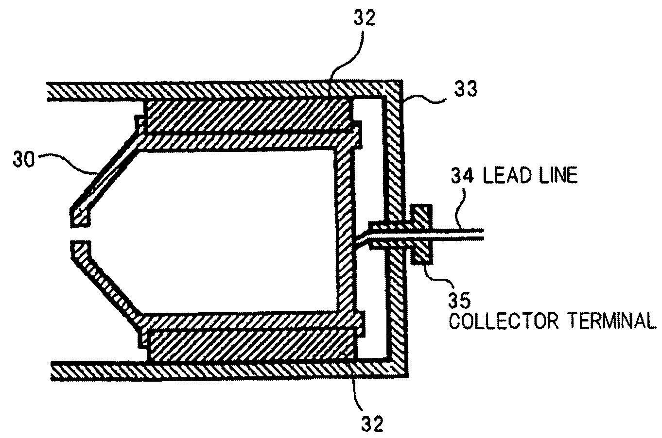
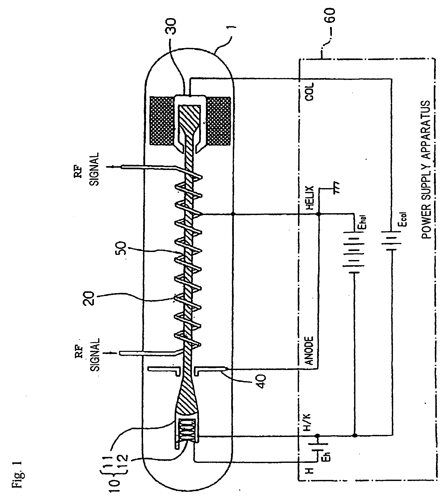
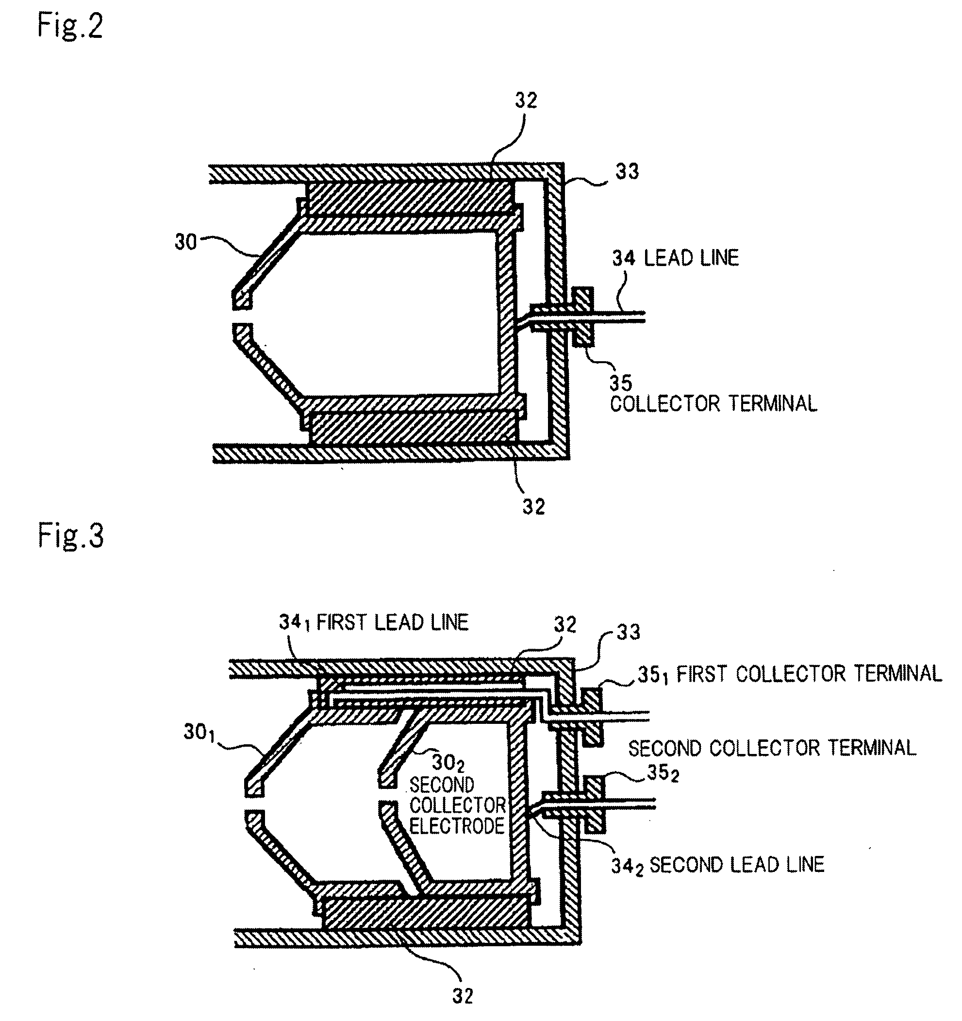
[0001]This application is based upon and claims the benefit of priority from Japanese patent application No. 2008-097121, filed on Apr. 3, 2008, the disclosure of which is incorporated herein in its entirety by reference.TECHNICAL FIELD[0002]The present invention relates to a collector that captures the beam of electrons emitted from an electron gun and an electron tube comprising the same.BACKGROUND ART[0003]A Traveling Wave Tube (TWT) or a klystron is an electron tube used for amplifying or oscillating a RF signal through interaction between a beam of electrons emitted from an electron gun and a high-frequency circuit.[0004]Referring to FIG. 1, a TWT 1 comprises electron gun 10 for emitting electrons, helix 20 functioning as a high-frequency circuit that allows electron beam 50 from electron gun 10 to interact with a RF signal (i.e., a microwave signal), collector 30 for collecting electron beam 50 passed through helix 20, and anode 40 for drawing out electron beam 50 from electro...

Claims


Application Information

Patent Timeline
IPC IPC(8): H01J25/34
CPCH01J23/027H01J25/34H01J23/0275
Inventor CHIBA, AKIRA
Owner NETCOMSEC
Learn More