
Crimping device for cranial cruciate ligament stabilization

a cranial cruciate ligament and stabilization technology, applied in the field of crimping devices for cranial cruciate ligament stabilization, can solve the problems of not allowing accurate adjustment of tension, and not allowing the use of larger suture materials, so as to maintain the tension, reduce the elongation of the loop, and maintain the effect of tension

Inactive Publication Date: 2009-10-01
WOTTON III HARRY
View PDF21 Cites 3 Cited by
  • Summary
  • Abstract
  • Description
  • Claims
  • Application Information

AI Technical Summary

Benefits of technology

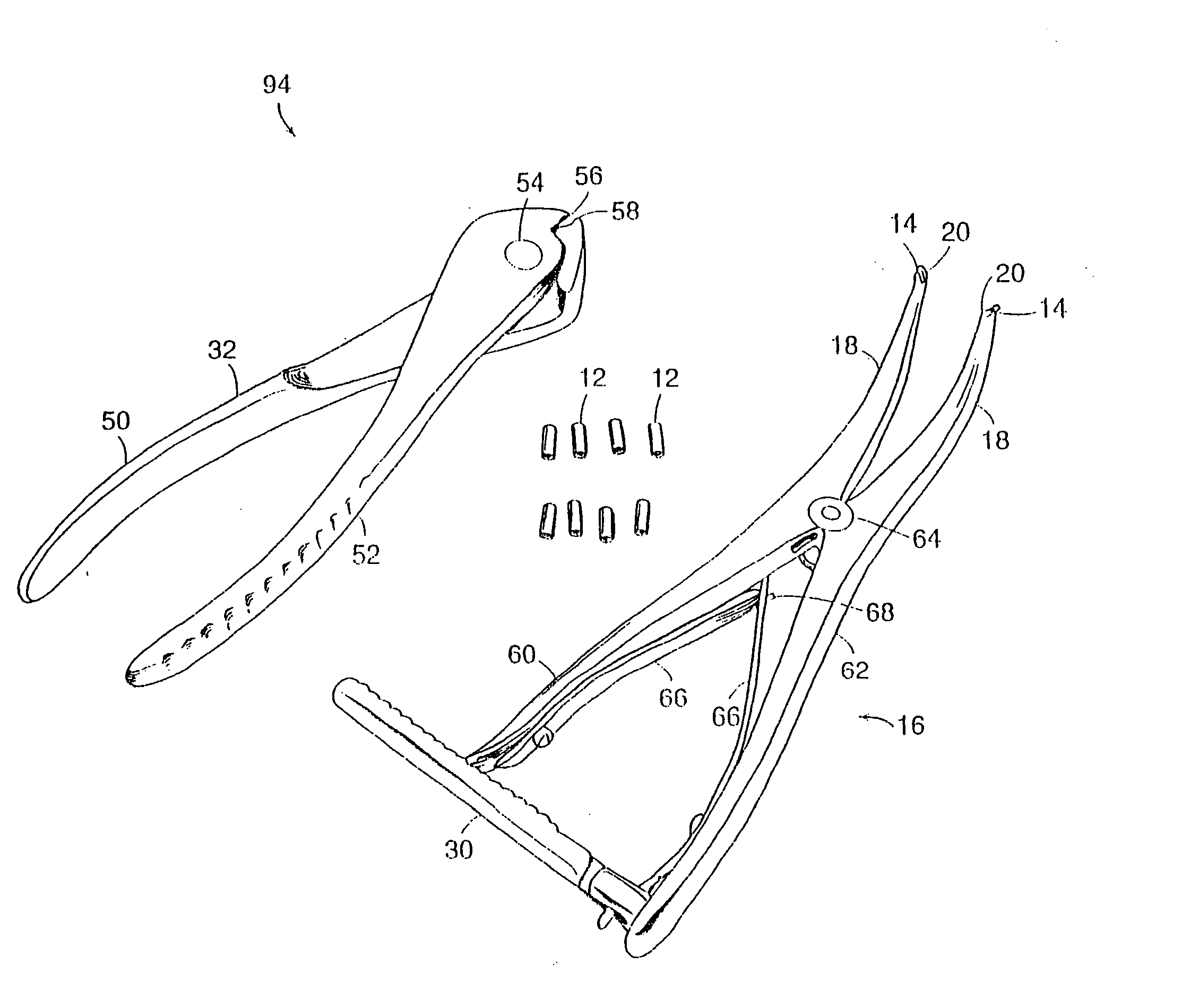
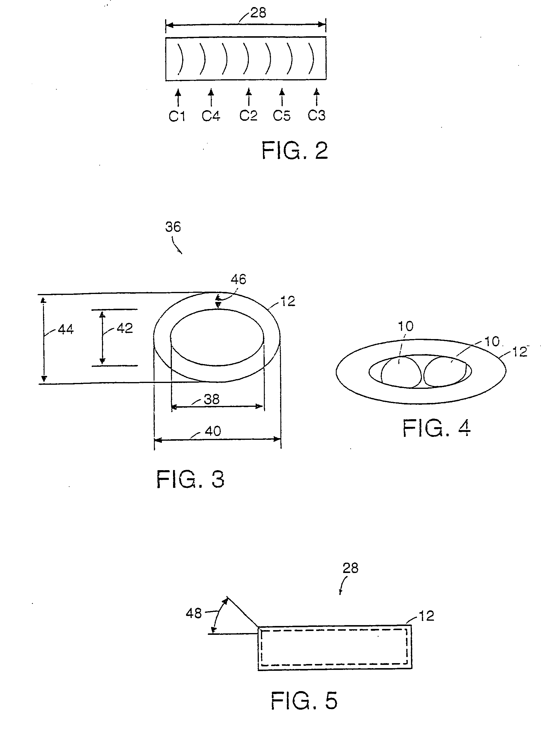
[0008]Preferably, the tensioning device will apply the appropriate tension, maintaining that tension while the surgeon checks the joint for movement. The tensioning device has an angle and slots at the distal tips so that the tips may slide over the suture and apply the tension against the secondary crimp clamps. The angle stops crimp clamp from sliding off the instrument. The crimp clamps are used in place of a knot to secure the suture, significantly reducing loop elongation. The crimp clamp has an oval cross section to allow the desired suture to be placed through its center and a specific material properties and wall thickness so that once it is crimped it will stay crimped. Further, a crimping tool is designed so that the exact amount of crimp is applied to the crimp clamp. The dimensions of the crimping area on the crimp tool are such that the crimp tool does not over crimp the suture, which would sever the material, nor does it under crimp the suture, allowing it to slip in the crimp tube. If one tried to crimp a tube using an instrument that was not specifically designed for crimping it would either over crimp the nylon that would cause the nylon to break or it would under crimp the nylon allowing it to slip.
[0009]Specifically, the tensioning device has an angle and slots at its distal tips. The slots allow the suture to be placed into the tips of the instrument allowing the secondary crimp clamps to rest against the outer edge of the tip. The angle ensures that the secondary crimp clamp will not slip off the tip during tightening. Preferably, there are ratchets in the handle of the instrument that locks the instrument at a variety of locations, therefore tension can be applied and than checked by the surgeon to ensure adequate tension in the joint. The angled tips of the tensioning device also allow the tool to function as a device to open up the joint to assess the damage and clean out any scar tissue.
[0010]This invention features a crimp tube crimping system including a crimping tool having: a first arm having a proximal end and a distal end, the proximal end comprising a first handle and the distal end comprising a first jaw, a second arm having a proximal end and a distal end, the proximal end comprising a second handle and the distal end comprising a second jaw, the second arm hingedly connected to the first arm, a first straight, flat crimping member integral with the first jaw of the first arm, the first crimping member having a first inner surface width, and a second straight, flat crimping member integral with the second jaw of the second arm, the second crimping member having a second inner surface width, the first and second straight, flat crimping members defining a gap therebetween when the first and second handles close and the crimping tool is in a fully closed position about the crimp tube, the first and second inner surface widths limiting further deformation of the crimp tube, the flat crimping members preventing cutting of a suture within the crimp tube.

Problems solved by technology

The DeAngelis technique does not allow for the accurate adjustment of tension to the stifle joint, it does not maintain the desired loop tension in the suture, and it does not allow larger suture material to be used.
Therefore it is hard to acquire the adequate / precise tension.
Also, due to the fact that a knot must be tied there is a limit on the size and strength of the material that can be used due to the suture resistance to bending, the memory of the material and the size of the resulting knot.
The DeAngelis / Lateral suture technique is particularly susceptible to loosening under repeated cyclic loading.
A slight amount of loosening due to cyclic loading reduces loop tension in the suture allowing internal rotation and cranial movement of the femur, which would result in lameness of the patient.

Method used


Image

  • Crimping device for cranial cruciate ligament stabilization
  • Crimping device for cranial cruciate ligament stabilization
  • Crimping device for cranial cruciate ligament stabilization

Examples


Embodiment Construction

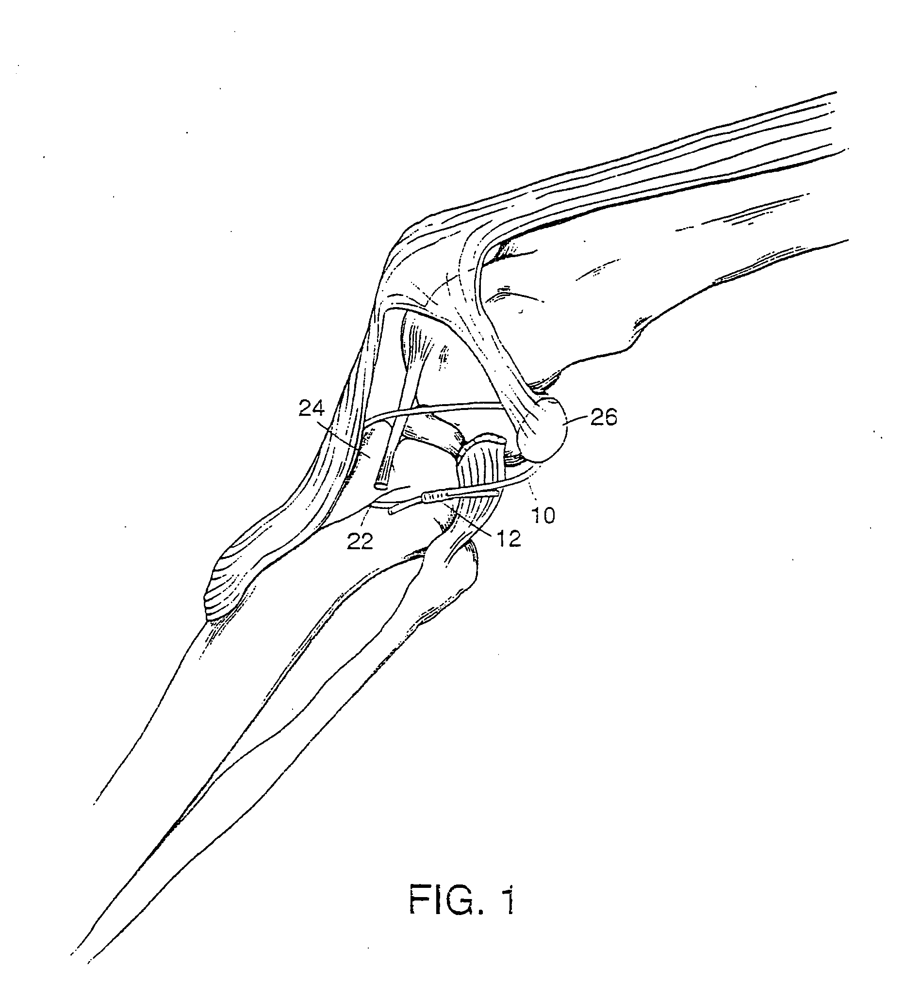
[0033]FIG. 1 is a perspective view of a lateral suture 10 used to stabilize the canine stifle incorporating a surgical crimp tube or clamp 12 that is used in place of a knot and the 80 lb. monofilament nylon. As is common in this technique, the monofilament nylon 10 is placed through a hole 22, which was drilled in the tibial tuberosity 24, and around the lateral fabella 26 using specially designed suture needles. The suture 10 is a hard type monofilament nylon with a tensile strength of 80 lbs. However, other sizes and brands of nylon are also commonly used. The surgical crimp clamp 12 is produced from implant grade, surgical stainless steel. The inside diameter edges of the crimp clamps have a slight chamfer, which is necessary, so that when the tube is crimped it will not damage the nylon.

[0034]The most extreme stresses occur once the animal starts to use the limb. When using a knot to secure the suture 10, this leads to premature loop elongation due to the knot becoming tighter....


PUM


Abstract

A crimp tube crimping system including a crimping tool having: a first arm having a proximal end and a distal end, the proximal end comprising a first handle and the distal end comprising a first jaw, a second arm having a proximal end and a distal end, the proximal end comprising a second handle and the distal end comprising a second jaw, the second arm hingedly connected to the first arm, a first straight, flat crimping member integral with the first jaw of the first arm, the first crimping member having a first inner surface width, and a second straight, flat crimping member integral with the second jaw of the second arm, the second crimping member having a second inner surface width, the first and second straight, flat crimping members defining a gap therebetween when the first and second handles close and the crimping tool is in a fully closed position about the crimp tube, the first and second inner surface widths limiting further deformation of the crimp tube, the flat crimping members preventing cutting of a suture within the crimp tube.

Description

RELATED APPLICATION[0001]This application is a divisional application of prior U.S. patent application Ser. No. 10 / 079,059, filed on Feb. 19, 2002, which was a continuation-in-part of U.S. patent application Ser. No. 09 / 537,651, filed Mar. 29, 2000, which claims the benefit of U.S. Provisional Application Ser. No. 60 / 172,918, filed Dec. 21, 1999, each of which are incorporated herein by reference.FIELD OF THE INVENTION[0002]This invention relates to a crimping device for cranial cruciate ligament stabilization.BACKGROUND OF THE INVENTION[0003]Cranial Cruciate (anterior cruciate) ligament stabilization systems are used on knees that have been traumatized resulting from excess interior rotation or excess cranial movement of the femur in respect to the tibia. An incision is made through lateral aspect of the stifle. The dermis layer is retracted in order to have adequate room to place the lateral suture. The lateral suture is placed, extra-articular, around the lateral fabella and thro...

Claims


Application Information

Patent Timeline
Patent Type & Authority Applications(United States)
IPC IPC(8): A61B17/00B25B7/02A61B17/04
CPCA61B17/0487A61B2017/0496A61B2017/0454
Inventor WOTTON, III, HARRY
Owner WOTTON III HARRY
Learn More