
Fastener with multiple threaded sections

a technology of threaded sections and fasteners, applied in the direction of threaded fasteners, screws, fastening means, etc., can solve the problems of slow screwing speed, insufficient space or void for accommodating, and large inserting torque, so as to improve the screwing effect and efficient guide debris ou

Inactive Publication Date: 2009-10-01
CHANNG CHIN IND CORP
View PDF4 Cites 12 Cited by
  • Summary
  • Abstract
  • Description
  • Claims
  • Application Information

AI Technical Summary

Benefits of technology

[0006]It is an object of the present invention to provide a screw with multiple threaded sections, which facilitates to increase the screwing speed, efficiently guide debris out and obtain a better screwing effect.
[0007]The present invention in conformity with the screw with multiple threaded sections essentially comprises a head, a triangular shank, and a drilling portion; wherein, the shank includes two opposite threaded sections with first and second threads, each of which performs in a triangular contour and has a sharp edge defined thereon; further, a third threaded section disposed on the drilling portion and has a planar flank formed to converge toward the sharp edge of the adjacent first thread. Therefore, the triangular threads and shank reduce the contact of the screw and the object while screwing for further reducing the frictional resistance and obtaining high screwing speed. The two opposite threaded sections can also assist the cutting debris in being efficiently extruded out of the object and provide a larger void to accommodate the remaining debris, thus preventing the crack of the object and permitting the screw to be firmly embedded into the object.

Problems solved by technology

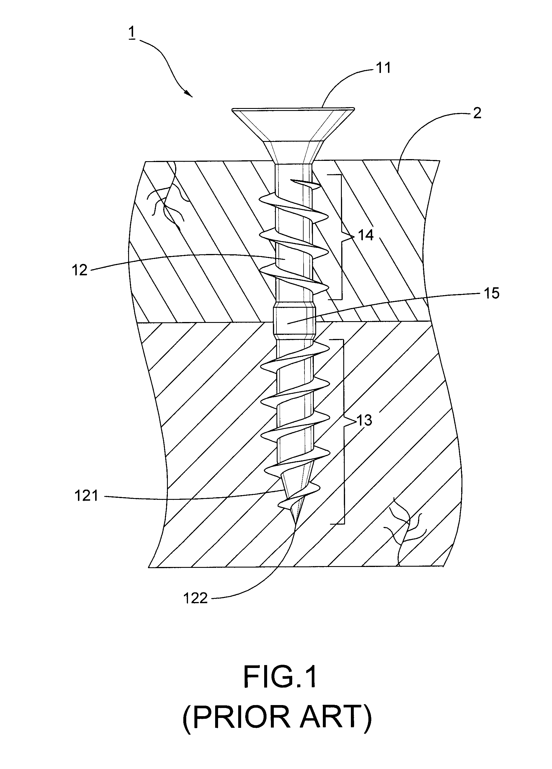
However, the circular threads and the shank 12 are unable to accommodate as much cutting debris and smoothly extrude the debris out of the surface of the object 2, therefore causing a larger inserting torque as well as a slower screwing speed while drilling the first threaded section 13 into the object 2.
Further, the debris generated from the region of the first threaded section 13 is moved back down via the assistance of the second opposite threaded section 14; the second threaded section 14 with circular threads, however, does not provide enough spaces or void for accommodating debris and retains accumulating it within the objects without guiding it out, hence the conventional screw 1 would result not only in increasing the screwing resistance but also rendering the object 2 to be subjected to the crack under the incessant accumulation therein.

Method used


Image

  • Fastener with multiple threaded sections
  • Fastener with multiple threaded sections
  • Fastener with multiple threaded sections

Examples


Embodiment Construction

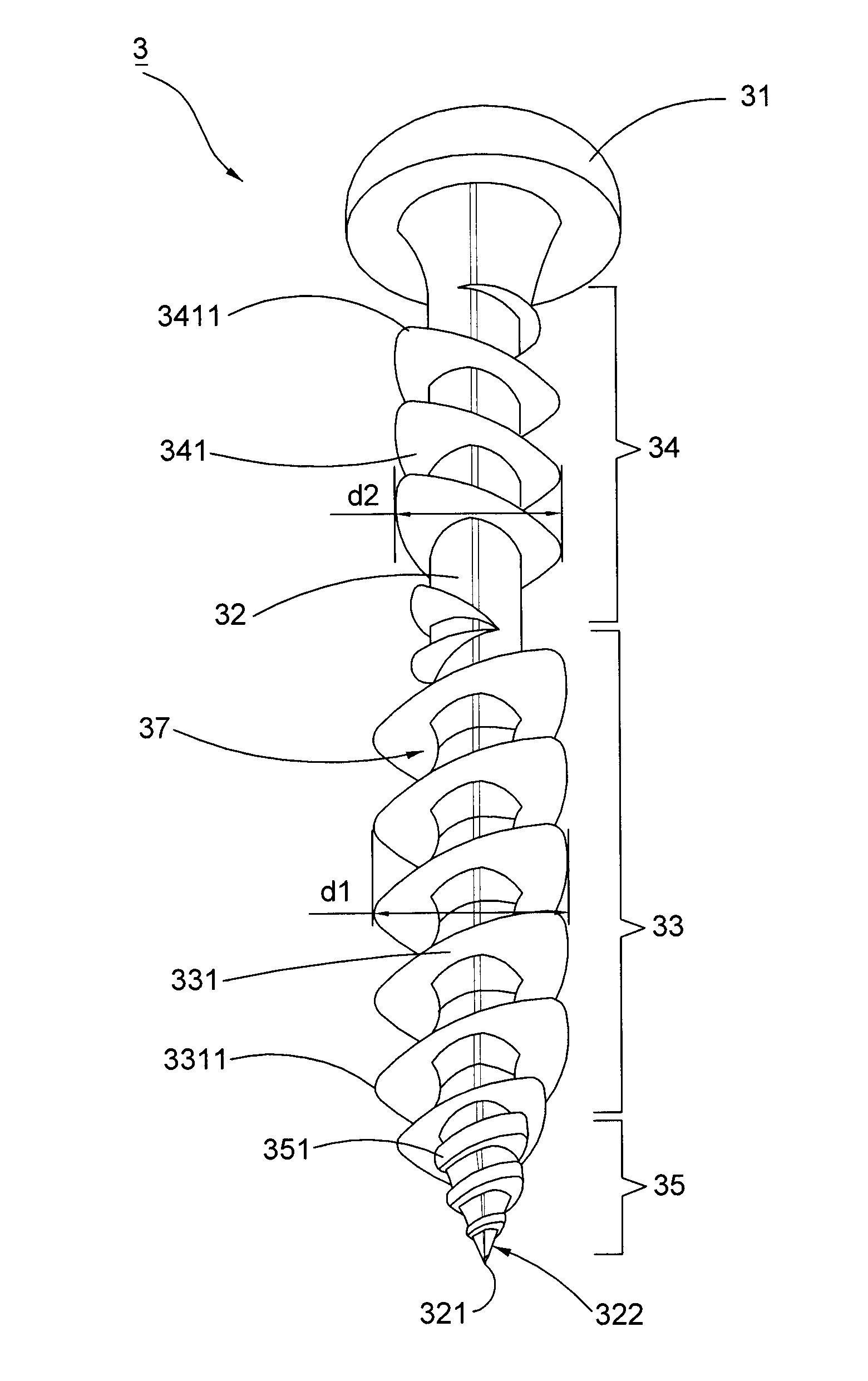
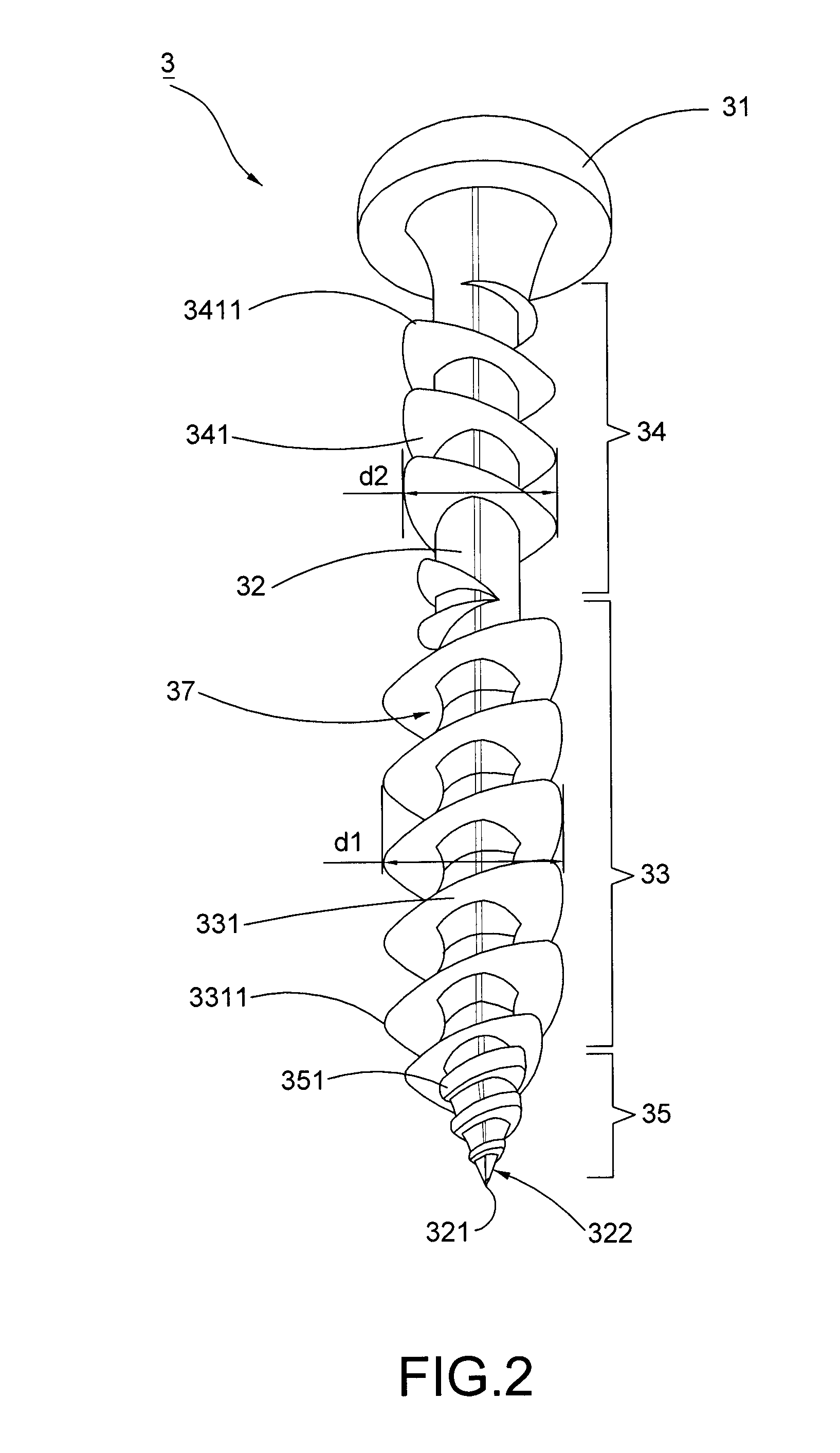
[0016]Referring to FIG. 2, a screw 3 of the first preferred embodiment comprises a screw shank 32, a screw head 31 formed on one end of the shank 32, a drilling portion 322 formed on the other end thereof, a first threaded section 33 spiraling round the screw shank 32, a third threaded section 35 disposed on the drilling portion 322 and a second threaded section 34 located between the first threaded section 33 and the head 31; wherein, the shank 32 is formed in a triangular contour, and the drilling portion 322 has a pointed tip 321 at its distal end. Further, the first threaded section 33 has a plurality of first threads 331 which are of triangular contours as well; each first thread 331 has a sharp edge 3311 formed on a periphery thereof.

[0017]Still further, the third threaded section 35 has a planar flank 351 formed thereon, and the planar flank 351 converges toward the sharp edge 3311 of the adjacent first thread 331 and contacts therewith. Additionally, the second threaded sect...


PUM


Abstract

The present invention pertains to a triangular shank with multiple threaded sections essentially including a head, a shank and a drilling portion. Wherein the shank has two opposite threaded sections formed in triangular and a third threaded section spiraling on the drilling portion. The third threaded section with a planar flank assists in enlarging the drilling track and providing guidance for those two threaded sections to easily enter into the object so as to efficiently extrude the debris out of the object and retain remaining debris for a better fastening effect. Further the triangular configuration results in the less contact between the screw and the object in time of screwing, thus reducing the frictional resistance and obtaining high screwing speed.

Description

BACKGROUND OF THE INVENTION[0001]1. Field of the Invention[0002]The present invention relates to a fastener, in particular to a screw with multiple threaded sections.[0003]2. Description of the Related Art[0004]A conventional screw 1 shown in FIG. 1 generally comprises a head 11, a cylindrical shank 12 extending therefrom, and two opposite threaded sections with separate circular threads namely a first threaded section 13 and a second threaded section 14 spiraling round the shank 12 and separated by a thread-free section 15; wherein, a drilling portion 121 is formed at the end of the shank 12 and has a pointed tip 122 formed at its free end, where the first threaded section 13 can be helically disposed.[0005]Still, in operation, the drilling portion 121 has a preliminary drilling into the object 2 for proceeding the subsequence cutting by the first threaded section 13. However, the circular threads and the shank 12 are unable to accommodate as much cutting debris and smoothly extrud...

Claims


Application Information

Patent Timeline
Patent Type & Authority Applications(United States)
IPC IPC(8): F16B35/04
CPCF16B5/0275F16B25/0047F16B2033/025F16B25/0078F16B25/103F16B25/0057
Inventor LIN, CHING-GUEIWU, MAU-CHANG
Owner CHANNG CHIN IND CORP
Learn More