
Varactor bank switching based on Anti-parallel branch configuration

a branch configuration and switching technology, applied in the direction of oscillator generators, electrical equipment, etc., can solve the problems of bank switch in the off-state becoming conductive, the switch transistor mb>1/b> can get turned on in the off-state, and the phase noise of the lc-tank vco may significantly degrad

Inactive Publication Date: 2009-10-01
IBM CORP
View PDF12 Cites 23 Cited by
  • Summary
  • Abstract
  • Description
  • Claims
  • Application Information

AI Technical Summary

Benefits of technology

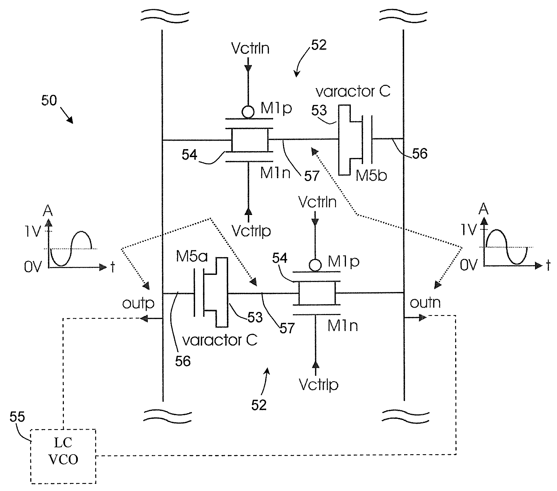
[0008]A system and apparatus for varactor bank switching for a voltage controlled oscillator is disclosed. One embodiment involves partitioning a varactor bank switch into two anti-parallel branches, wherein each branch comprises a pass-gate circuit that is series-connected to a varactor or a fixed capacitor; and maintaining an output common mode voltage of an actual oscillator signal at the varactor-side output terminal of each pass-gate circuit, such that a threshold voltage is not exceeded and the switch remains in an off-state.

Problems solved by technology

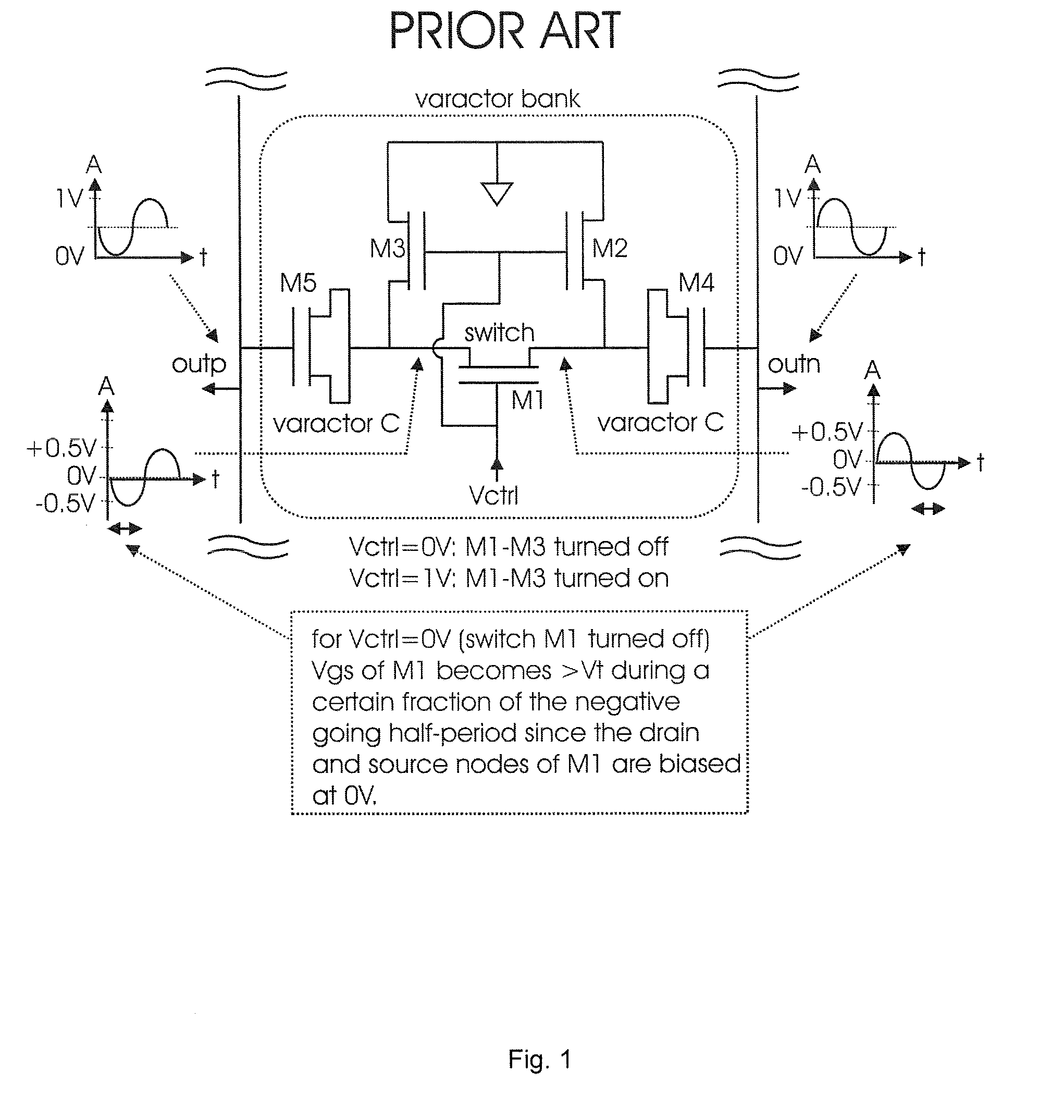
If the varactor bank switches in the off-state become conductive during certain fractions of the oscillation period, the phase noise of the LC-tank VCO may significantly degrade. FIG. 1 shows a schematic of a conventional varactor bank circuit, illustrating the problem that the varactor bank switch in the off-state becomes conductive during certain fractions of the oscillation period.
A disadvantage of the circuit in FIG. 1 is that the switch transistor M1 can get turned on in the off-state, if the source potential becomes sufficiently negative such that Vgs of M1 is higher than the threshold voltage Vth despite the gate potential of M1 is 0V (i.e., the control signal Vctrl is 0V).

Method used


Image

  • Varactor bank switching based on Anti-parallel branch configuration
  • Varactor bank switching based on Anti-parallel branch configuration
  • Varactor bank switching based on Anti-parallel branch configuration

Examples


Embodiment Construction

[0017]The following description is made for the purpose of illustrating the general principles of the invention and is not meant to limit the inventive concepts claimed herein. Further, particular features described herein can be used in combination with other described features in each of the various possible combinations and permutations. Unless otherwise specifically defined herein, all terms are to be given their broadest possible interpretation including meanings implied from the specification as well as meanings understood by those skilled in the art and / or as defined in dictionaries, treatises, etc.

[0018]The description may disclose several preferred embodiments of varactor banks, as well as operation and / or component parts thereof. While the following description will be described in terms of varactor bank for LC-tank voltage controlled oscillators for clarity and to place the invention in context, it should be kept in mind that the teachings herein may have broad applicatio...


PUM


Abstract

A system and apparatus for varactor bank switching for a voltage controlled oscillator, is disclosed. Varactor bank switching involves partitioning a varactor bank switch into two anti-parallel branches, wherein each branch comprises a pass-gate circuit that is series-connected to a fixed varactor or capacitor; and maintaining an output common mode voltage of an actual oscillator signal at the varactor-side terminal of each pass-gate circuit, such that a threshold voltage of the switch transistor in the pass-gate circuit is not exceeded and the switch remains in an off-state.

Description

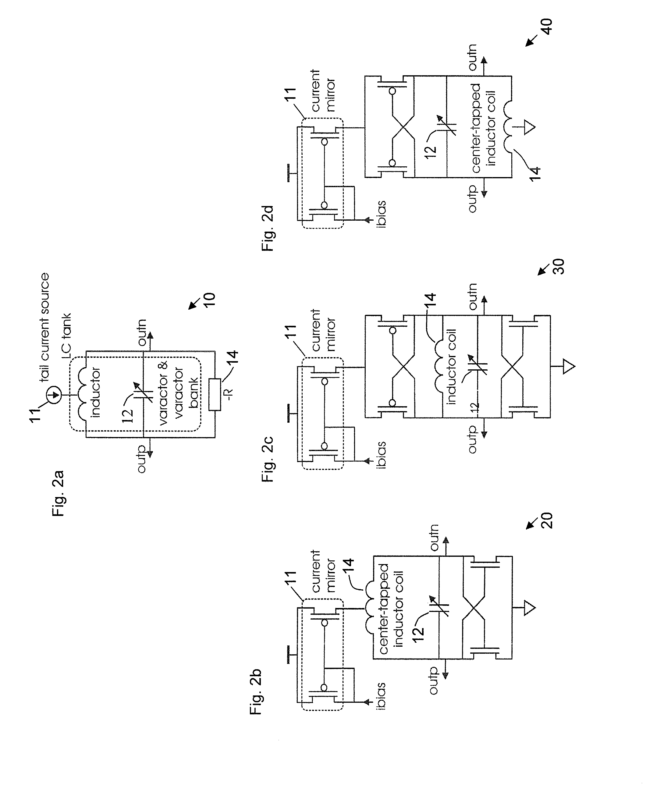
BACKGROUND OF THE INVENTION[0001]1. Field of the Invention[0002]The present invention relates generally to varactor bank switching, and in particular to configuration of varactor bank switches.[0003]2. Background Information[0004]Varactor banks are applied in LC-tank voltage controlled oscillators (VCO) to perform a coarse tuning of the oscillation frequency. LC-tank oscillators are typically used in communication systems, such as in generating high frequency oscillator signals in microwave or radio frequency apparatus. A typical LC-tank circuit includes inductors (L) and capacitors (C) configured in a circuit such that the inductors and capacitors oscillate because of current or voltage exchange between inductors and capacitors at a specified frequency. To achieve a high Cmax / Cmin-ratio, switches are used in the varactor bank, where Cmax and Cmin denote the maximum and minimum capacitance values of the varactor at e.g. a logical low and high biasing voltage. If the process technolo...

Claims


Application Information

Patent Timeline
IPC IPC(8): H03B5/12
CPCH03B2201/0208H03B2201/025H03B5/1253H03B5/1215H03B5/1265H03B5/1228
Inventor KOSSEL, MARCEL A.MORF, THOMAS E.WEISS, JONAS R.
Owner IBM CORP
Learn More