
Al-based alloy sputtering target and manufacturing method thereof

a technology of sputtering target and al-based alloy, which is applied in the direction of vacuum evaporation coating, electrolysis components, coatings, etc., can solve the problems of gd, nd) alloy, particularly effective splash prevention countermeasure, etc., and achieve excellent heat resistance and low electrical resistivity

Inactive Publication Date: 2009-10-01
KOBELCO RES INST +1
View PDF28 Cites 27 Cited by
  • Summary
  • Abstract
  • Description
  • Claims
  • Application Information

AI Technical Summary

Benefits of technology

[0014]As has been described above, a countermeasure for preventing the splash is disclosed to some extent, for example, in Al—Ni-rare earth element alloys or Al—Ti—W alloys. However, it is considered that the splash preventive technique is different also depending on the kind of the sputtering target. The present inventors have already found that when an Al—(Ni, Co)—(Cu, Ge)—(La—Gd—Nd) alloy is used, the Al-based alloy film formed of the material and a pixel electrode comprising a conductive oxide film can be in direct contact with each other and, further, low electrical resistivity and excellent heat resistance can be obtained even in a case where the heating treatment temperature after contact is relatively low. However, a splash preventive countermeasure which is particularly effective in a case where the sputtering target is an Al—(Ni, Co)—(Cu, Ge)—(La, Gd, Nd) alloy has not yet been established.
[0048]According to the invention, since the Al—(Ni, Co)—(Cu, Ge)—(La, Gd, Nd) alloy is used as the sputtering target and the Vickers hardness (HV) of the sputtering target is appropriately controlled, generation of abnormal discharge in the initial stage, particularly, generation of initial splashing at the initial stage of using the sputtering target is decreased. Accordingly, defects generated in interconnection films or the like by the splashing can be prevented and, as a result, yield of FPD can be improved and the operation performance of FPD can be improved.

Problems solved by technology

However, a splash preventive countermeasure which is particularly effective in a case where the sputtering target is an Al—(Ni, Co)—(Cu, Ge)—(La, Gd, Nd) alloy has not yet been established.

Method used


Image

  • Al-based alloy sputtering target and manufacturing method thereof
  • Al-based alloy sputtering target and manufacturing method thereof
  • Al-based alloy sputtering target and manufacturing method thereof

Examples


example 1

[0106]Al-based alloy preforms (density: about 50 to 60%) were obtained by a spray forming method using Al—Ni—Cu—La alloys under various conditions as shown in Tables 1 and2.

(Spray Forming Conditions)

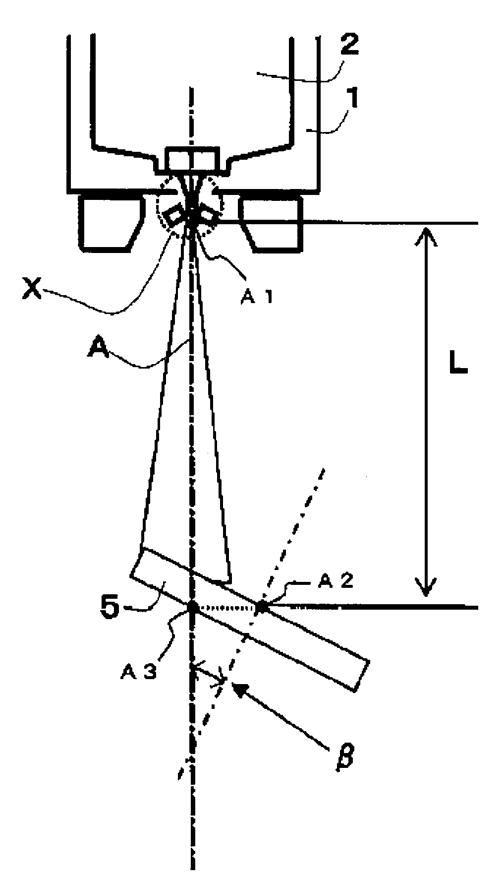
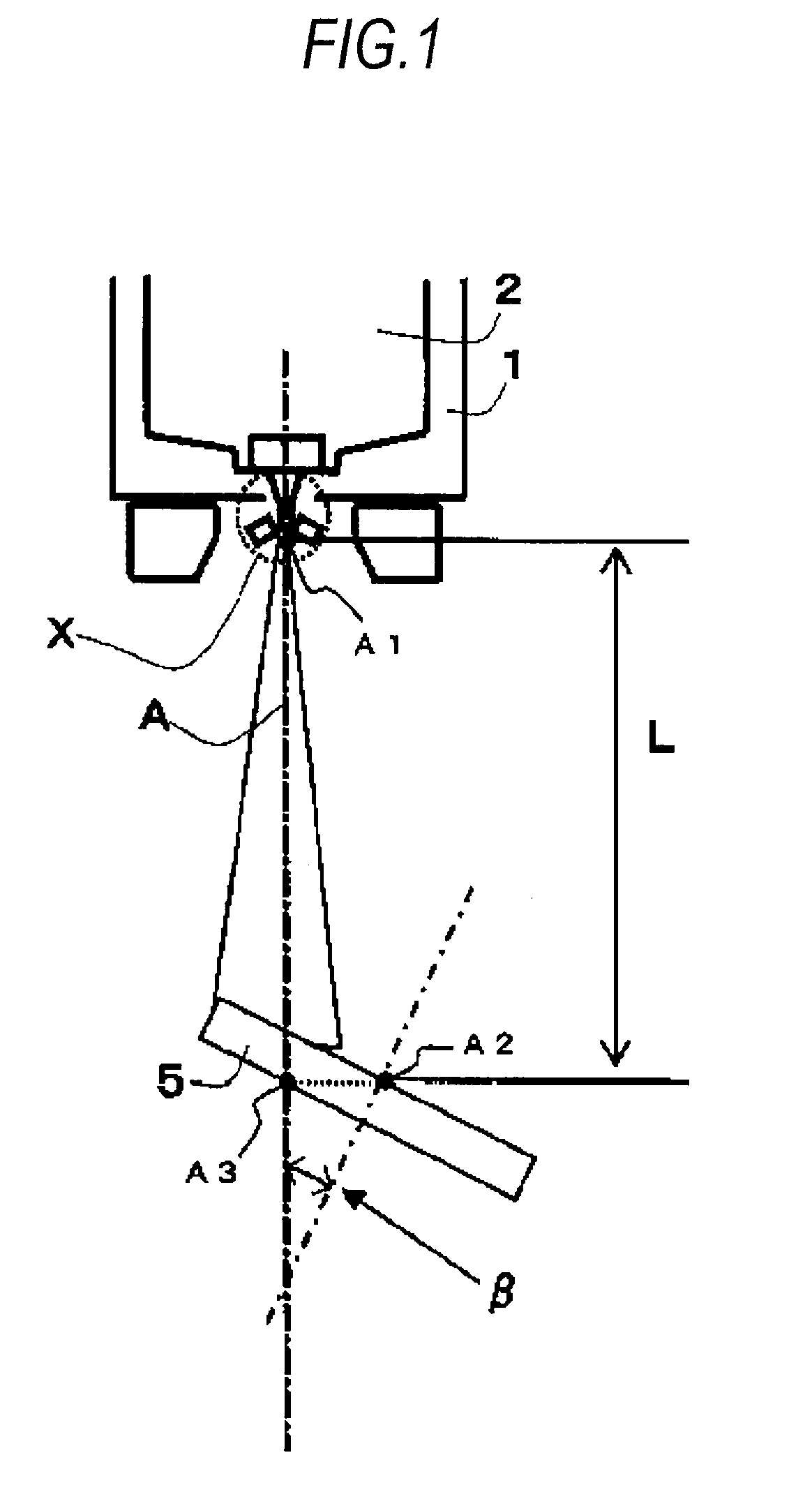
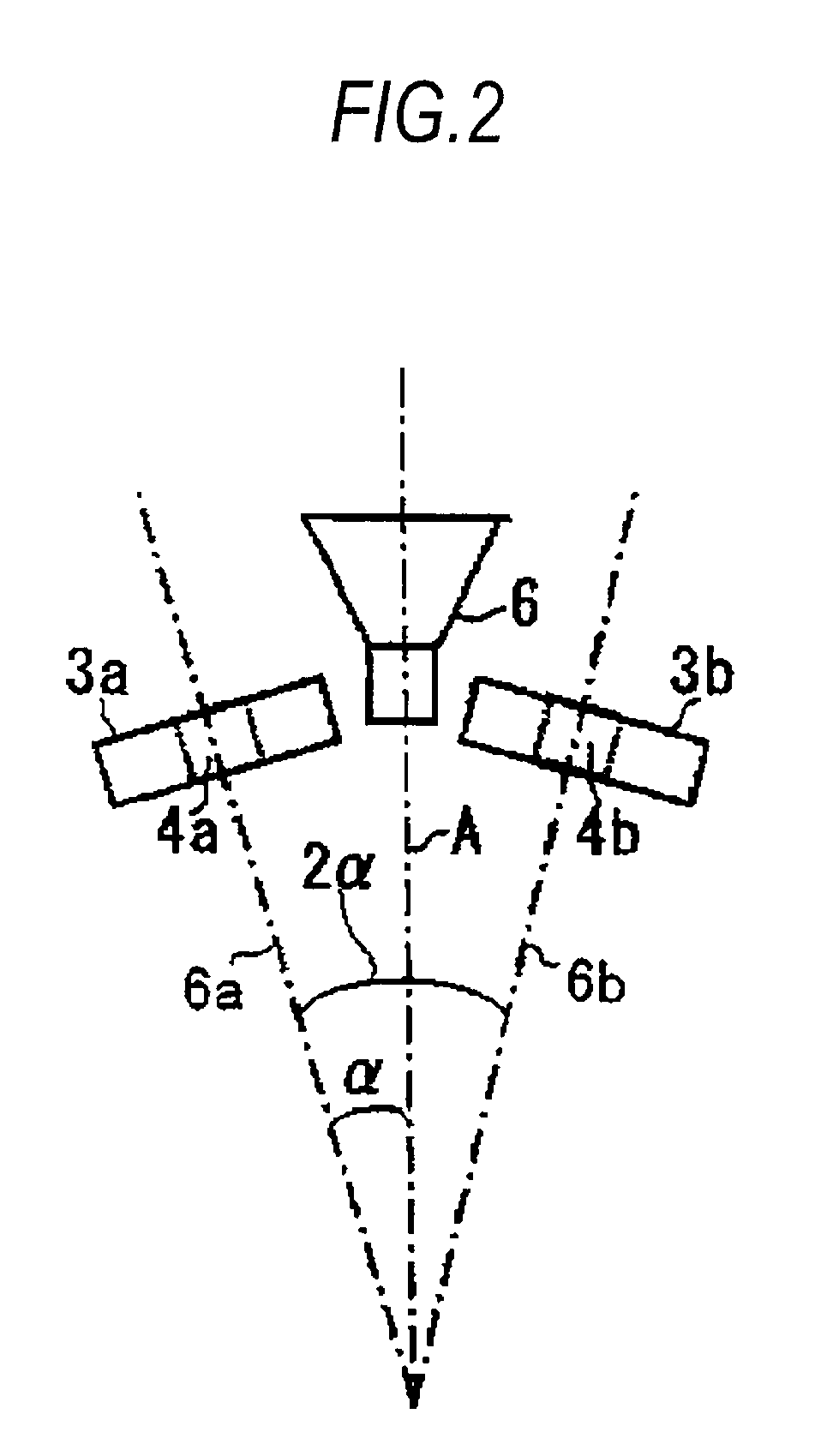
[0107]Melting temperature: 800 to 1100° C. (refer to Tables 1 and 2)[0108]Gas / metal ratio: 5 to 8 Nm3 / kg (refer to Tables 1 and 2)[0109]Spray distance: 800 to 1300 mm (refer to Tables 1 and 2)[0110]Exit angle α of gas atomizer (refer to FIG. 2): 7°[0111]Collector angle β: 35°

[0112]The thus obtained preform was encapsulated and degassed in a capsule and hot isostatic pressing (HIP) was performed to the entire capsule to obtain a dense body of an Al—Ni—Cu—La alloy. The HIP treatment was performed at an HIP temperature of 550° C., at an HIP pressure of 85 MPa, and for an HIP time of 2 hours.

[0113]Then, after forging the obtained dense body into a plate-like metal material and, further, rolling the same such that the plate thickness was mostly identical with that of a final product (sputteri...

example 2

[0141]Next, Al-based alloy sputtering targets (specimens) were manufactured in the same manner as in Example 1 (except the conditions shown in Tables 3 and 4) by using the Al—Co—Ge—La alloys as shown in Tables 3 and 4 (Nos. 34 to 66). The Vickers hardness (HV) was measured for the Al-based sputtering targets obtained, and the generation of initial splashing was evaluated by conducting the sputtering test.

TABLE 3Number ofTemperaturegenerationPass / failureof heatof initialjudgment forMeltingGas / MetalSprayRollingtreatment orVickerssplashingdecreasingCoGeLatemperatureratiodistancetemperatureannealinghardness(Number / initialNo.(at %)(at %)(at %)(° C.)(Nm3 / kg)(mm)(° C.)(° C.)(HV)cm2)splashing340.050.50.29508100040025038.37A350.20.50.29508100040025042.55A361.00.50.29508100040025047.73A371.50.50.29508100040025051.62A380.20.10.29508100040025036.87A390.20.50.29508100040025042.55A400.21.00.29508100040025044.34A410.20.50.19508100040025039.46A420.20.50.29508100040025042.55A430.20.51.09508100040025...

example 3

[0152]Next, Al-based alloy sputtering targets (specimens) were manufactured in the same manner as in Example 1 (except the conditions shown in Tables 5 and 6) by using the Al—Ni—Ge—Nd alloys as shown in Tables 5 and 6 (Nos. 67 to 99). The Vickers hardness (HV) was measured for the Al-based sputtering targets obtained, and the generation of initial splashing was evaluated by conducting the sputtering test.

TABLE 5Number ofTemperaturegenerationPass / failureof heatof initialjudgment forMeltingGas / MetalSprayRollingtreatment orVickerssplashingdecreasingNiGeNdtemperatureratiodistancetemperatureannealinghardness(Number / initialNo.(at %)(at %)(at %)(° C.)(Nm3 / kg)(mm)(° C.)(° C.)(HV)cm2)splashing670.050.50.59508100040025040.16A680.10.50.59508100040025041.45A691.00.50.59508100040025053.91A701.50.50.59508100040025056.01A710.10.10.59508100040025037.57A720.10.50.59508100040025041.45A730.11.00.59508100040025046.14A740.10.50.19508100040025036.47A750.10.50.59508100040025041.45A760.10.51.09508100040025...


PUM

PropertyMeasurementUnit
distanceaaaaaaaaaa
temperatureaaaaaaaaaa

Abstract

The present invention provides an Al—(Ni, Co)—(Cu, Ge)—(La, Gd, Nd) alloy sputtering target capable of decreasing a generation of splashing in an initial stage of using the sputtering target, preventing defects caused thereby in interconnection films or the like and improving a yield and operation performance of an FPD, as well as a manufacturing method thereof. The invention relates to an Al-based alloy sputtering target which is an Al—(Ni, Co)—(Cu, Ge)—(La, Gd, Nd) alloy sputtering target comprising at least one member selected from the group A (Ni, Co), at least one member selected from the group B (Cu, Ge), and at least one member selected from the group C (La, Gd, Nd) wherein a Vickers hardness (HV) thereof is 35 or more.

Description

CROSS-REFERENCE TO RELATED APPLICATIONS[0001]This application claims priority from Japanese Patent Application No. 2008-093264 filed on Mar. 31, 2008, the entire subject matter of which is incorporated herein by reference.BACKGROUND OF THE INVENTION[0002]1. Field of the Invention[0003]The present invention relates to an Al-based alloy sputtering target containing at least one member selected from a group A (Ni, Co), at least one member selected from a group B (Cu, Ge), and at least one member selected from a group C (La, Gd, Nd), respectively (hereinafter referred to as “Al—(Ni, Co)—(Cu, Ge)—(La, Gd, Nd) alloy), and a manufacturing method thereof. Specifically the invention relates to an Al-based alloy sputtering target capable of decreasing initial splashing generated in an initial stage of sputtering upon depositing a thin film by using a sputtering target, and a manufacturing method thereof.[0004]2. Description of the Related Art[0005]Al-based alloys have been used generally with...

Claims


Application Information

Patent Timeline
Patent Type & Authority Applications(United States)
IPC IPC(8): C23C14/34C21D1/00
CPCC22C21/00C23C14/3414C22F1/04
Inventor TAKAGI, KATSUTOSHIIWASAKI, YUKIEHIRA, MASAYAGOTO, HIROSHIMIKI, AYAOKUNO, HIROYUKIOCHI, MOTOTAKAKISHI, TOMOYA
Owner KOBELCO RES INST
Learn More