Eureka AIR delivers breakthrough ideas for toughest innovation challenges, trusted by R&D personnel around the world.

Sequential start clutch for a material mixing machine

a technology of a clutch and a material mixing machine, which is applied in the field of clutches, can solve the problems of reducing the startup torque and staggered startup of the auger, and achieve the effect of reducing the startup load

Active Publication Date: 2009-09-24
KUHN NORTH AMERICA
View PDF6 Cites 27 Cited by
  • Summary
  • Abstract
  • Description
  • Claims
  • Application Information

AI Technical Summary

Benefits of technology

[0007]Accordingly, one aspect of the present invention provides a device that reduces the startup load placed on the power source or drive train of a mixing or material spreading machine using multiple rotating parts.
[0008]One aspect of the invention provides for the use of less than a maximum number for augers, for example, only one auger, during startup, and then starting one or more additional augers later. This arrangement reduces the startup torque, and in effect, staggers the startup of the augers over time. In the case of a two-auger system, delaying the start of the second auger to a time after the first auger is rotating will reduce the startup torque by half when the first and second augers have equal startup torques. One benefit of this arrangement is that the mixer is started with less power, and less stress is placed on the drivelines and power source.

Problems solved by technology

This arrangement reduces the startup torque, and in effect, staggers the startup of the augers over time.

Method used


Image

  • Sequential start clutch for a material mixing machine
  • Sequential start clutch for a material mixing machine
  • Sequential start clutch for a material mixing machine

Examples


Embodiment Construction

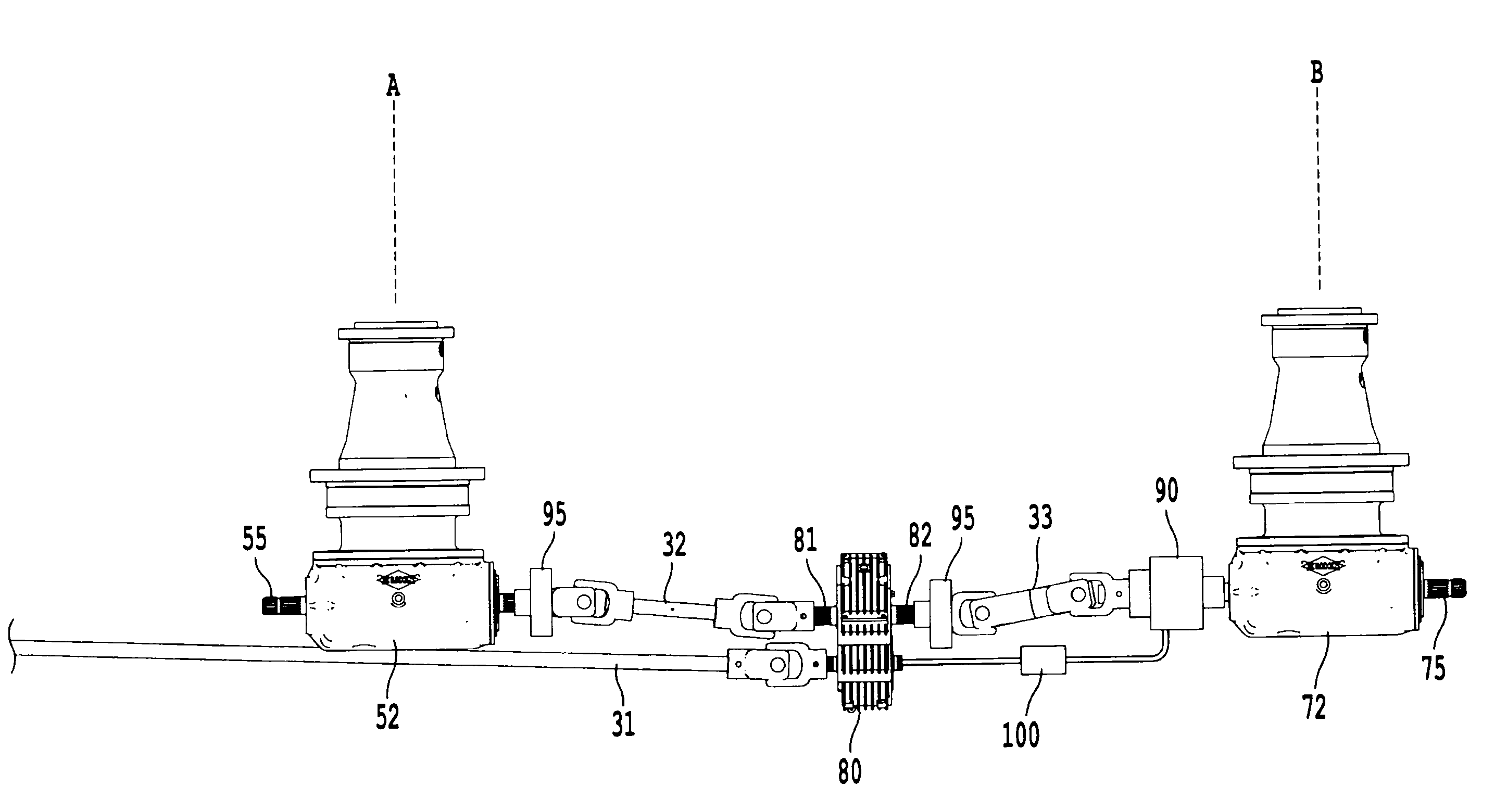
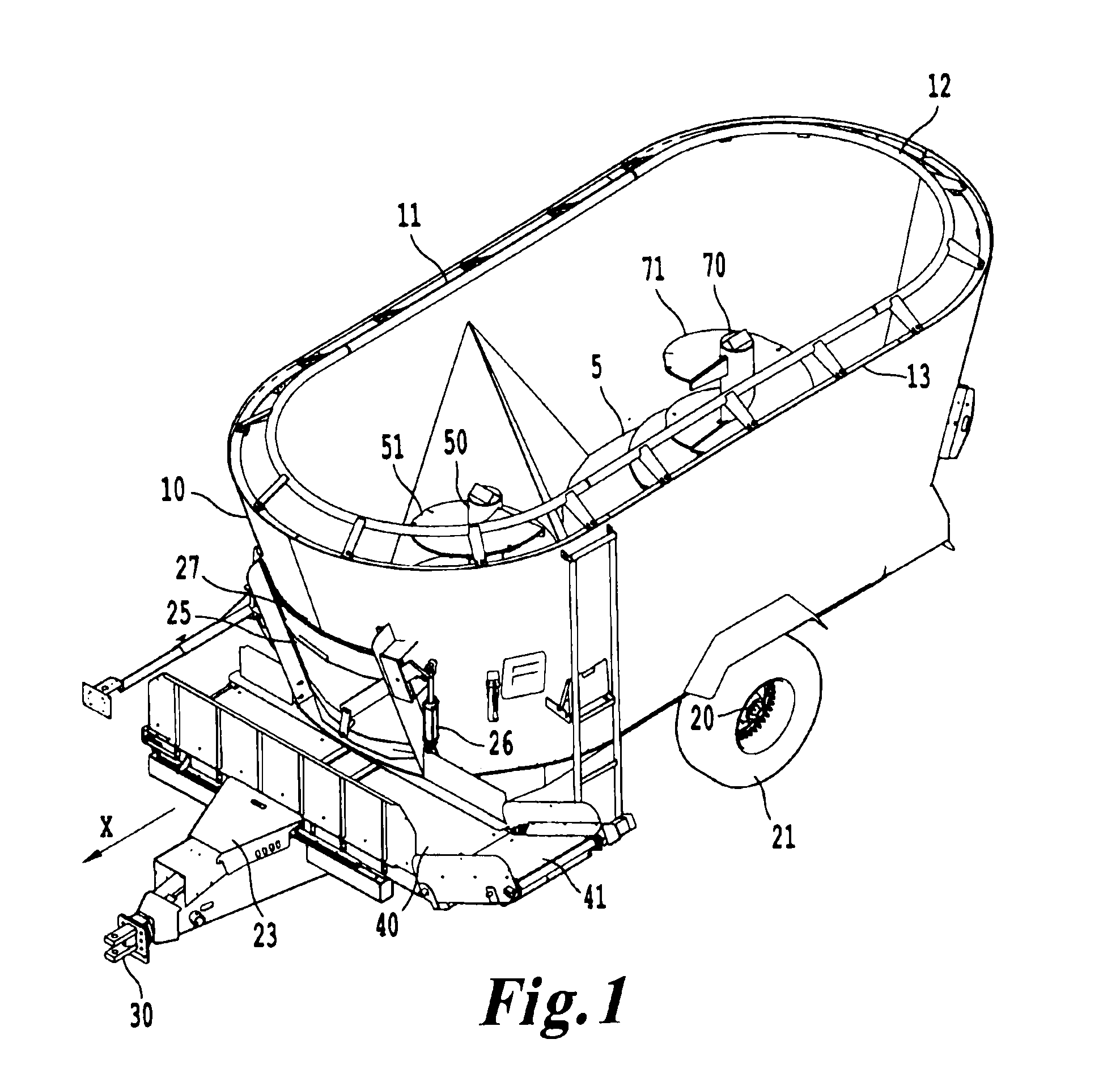
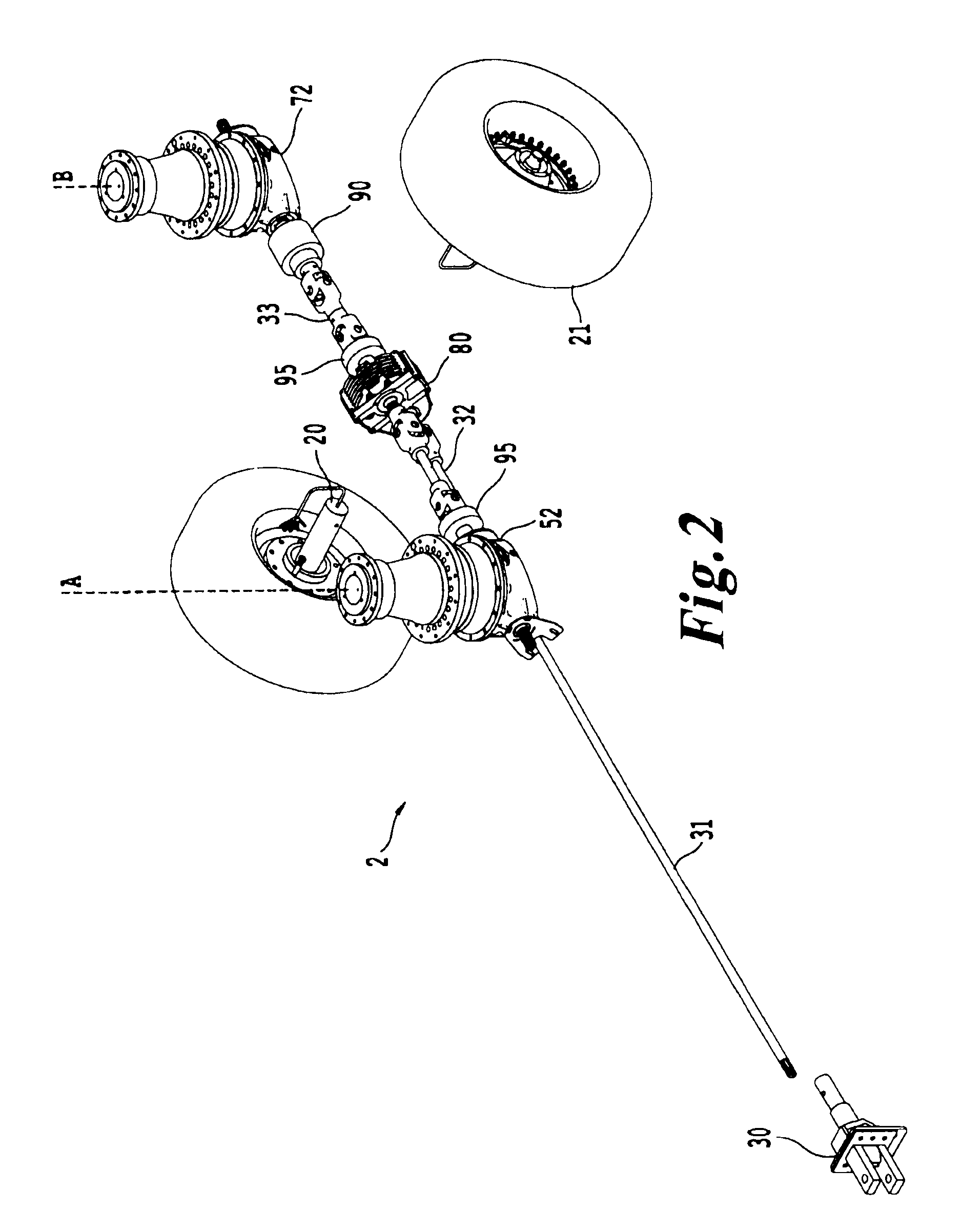
[0026]With reference to FIG. 1, an isometric view of one example of a sequential start clutch system installed in a mixer 1 is shown. The mixer 1 includes a drive panel 5. In this example, the drive panel 5 is the floor of the mixer 1. In the example shown in FIG. 1, a first auger 50 and a second auger 70 are connected through the drive panel 5 to a drive train.

[0027]The mixer 1 also includes a front wall 10, a right side wall 11, a rear wall 12, and a left side wall 13. Typically, these side walls will, in combination with the drive panel 5, form a container such as a mixing chamber with one open face through which material can be deposited. In the embodiment shown in FIG. 1, the open face is the top of the mixer 1. In an alternate embodiment, the drive panel 5 is a wall of the container instead of part of the floor of the container.

[0028]As further shown in FIG. 1, the front wall 10 includes a door 25 covering an opening 27. The door 25 preferably slides to expose an opening 27 di...


PUM


Abstract

A mixer system includes a mixing chamber with a drive panel, open top, discharge opening in a side of the mixing chamber, and door configured to open and close the discharge opening. A first mixing auger is disposed inside the mixing chamber, and a first auger drive is disposed on another side of the drive panel and connected to the first auger through the drive panel and connected to a driveline. A second mixing auger is disposed inside the mixing chamber on the first side of the drive panel, and another auger drive is connected to the second auger through the drive panel. A clutch is connected between the second auger drive and the driveline and configured to mechanically connect and disconnect the second auger drive from the driveline based on an input. A method of sequentially starting different augers within a mixing chamber is provided.

Description

BACKGROUND OF THE INVENTION[0001]1. Field of the Invention[0002]This invention relates to a clutch system configured to reduce a load on a power transmission device upon activation. One application of the device relates to a sequential start clutch system applied to a mixing machine such as a feed mixer, manure spreader, or aggregate mixer.[0003]2. Description of the Related Art[0004]Various types of equipment for mixing, chopping, liquefying, or distributing material are available. Some use two or more components configured to rotate. In one agricultural application, a mixing machine uses two or more augers disposed inside a container configured to rotate around separate axes. The augers are typically powered by a common power source such as a power-take-off (PTO) connected to a motor.[0005]It can take a tremendous amount of power to start a multiple auger device when the machine is filled with material, and especially if the device holds a heavy material such as manure, aggregate ...

Claims


Application Information

Patent Timeline
Patent Type & Authority Applications(United States)
IPC IPC(8): B01F15/00B01F5/12B01F7/16G06F19/00B01F25/60
CPCB01F7/085F16D48/02B01F7/241F16D2048/0209F16D2500/1026F16D2500/3024F16D2500/7041B01F27/723B01F27/922
Inventor MCFARLANE, CLAUDEALBRIGHT, CHRISBASSETT, WILLIAM
Owner KUHN NORTH AMERICA
Why Eureka
Eureka Blog
Learn More