
Nut

Active Publication Date: 2009-09-10
TANEICHI KAORU
View PDF4 Cites 12 Cited by
  • Summary
  • Abstract
  • Description
  • Claims
  • Application Information

AI Technical Summary

Benefits of technology

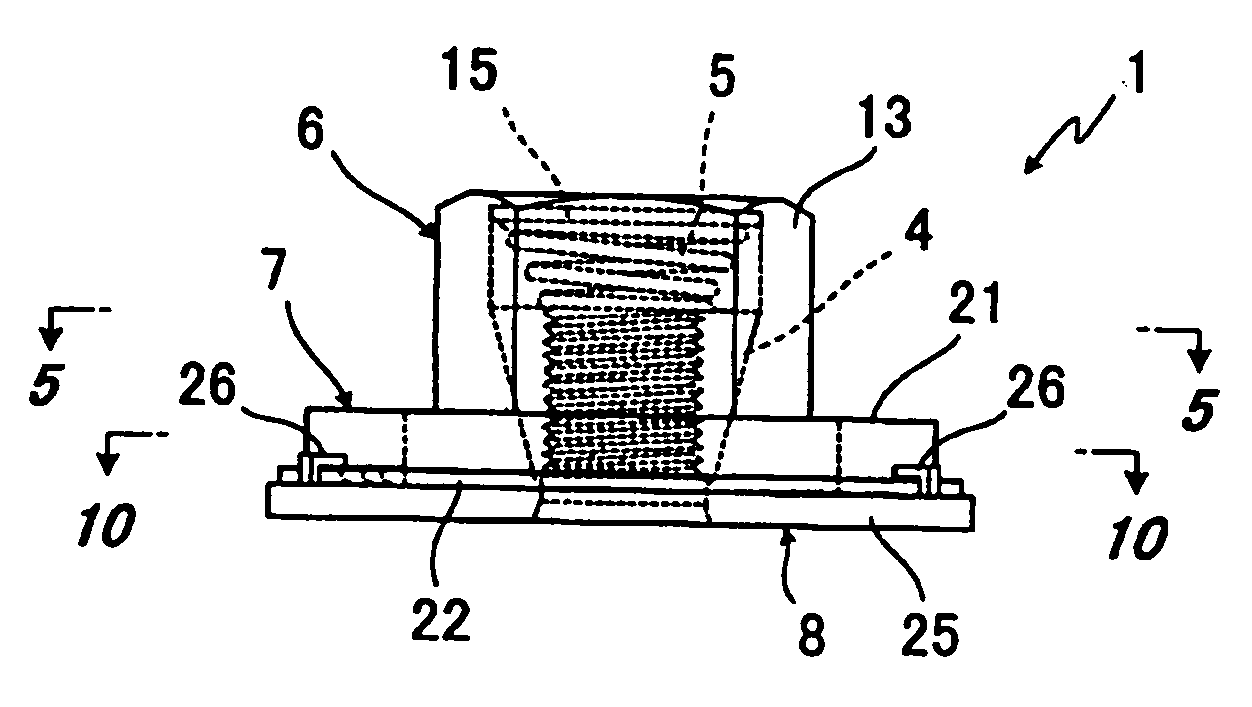
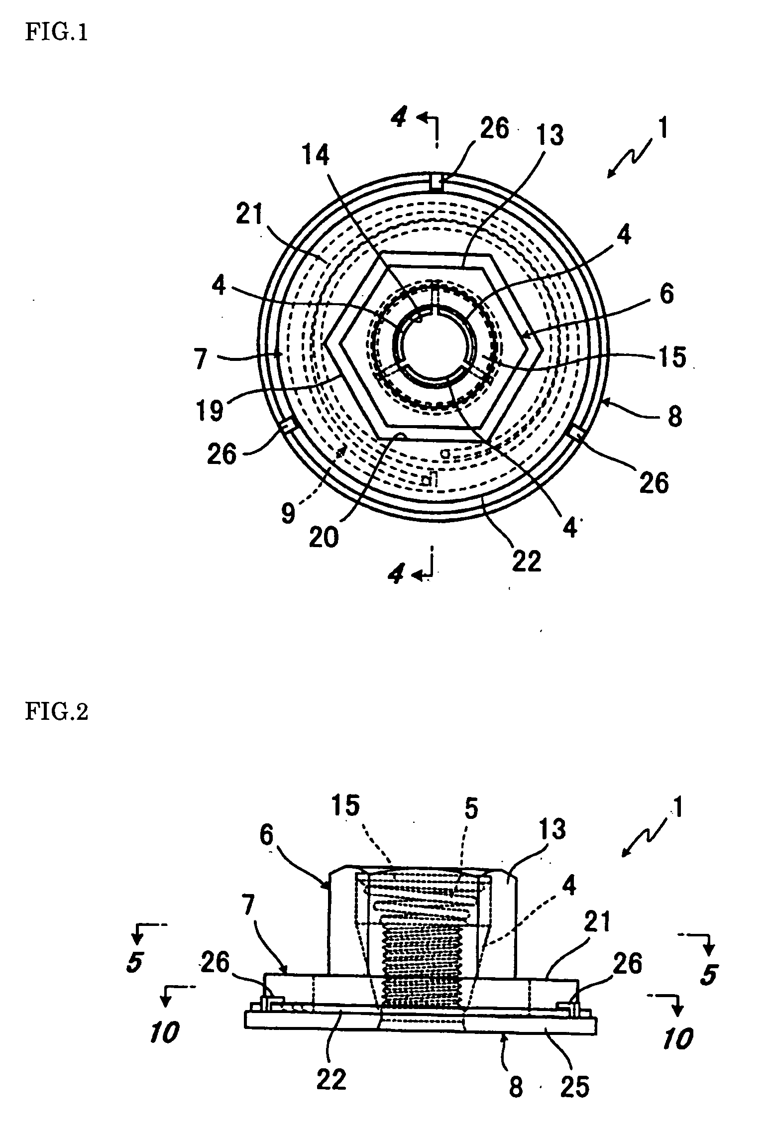
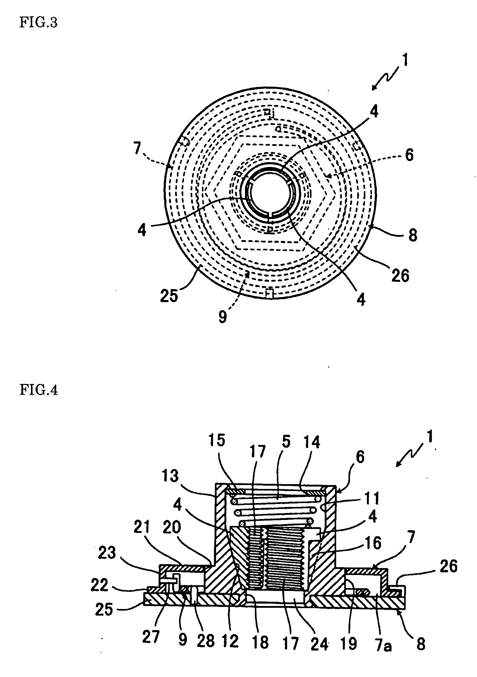
[0005]In view of the conventional drawback as described above, it is an object of the present invention to provide a nut which, when it is fitted on the bolt and rotated in the tightening direction, at least the three or more nut segments are screwed on to the thread of the bolt, causing the nut body in which the nut segments are received to be constantly urged in the tightening direction, which eliminates play of the nut segments to keep the nut and the bolt in a state where they are reliably screwed to each other.
[0013](2) As described in the above (1), because the nut is attached to the nut body, it is easy to handle and can be used just like conventional nuts.
[0014](3) As described in the above (1), addition of a spring case and a nut body urging spring is all that is needed, so that it can be produced easily.

Problems solved by technology

However, a drawback is that there may or may not always be a clearance about one pitch width of a thread.

Method used


Image

  • Nut
  • Nut
  • Nut

Examples


second embodiment

[0061]A nut 1B constructed as the above will have similar action effects to that to practice the present invention.

[0062]A fourth embodiment to practice the present invention is shown in FIGS. 19 to 21. It is distinguished from the first preferred embodiment that: a spring case 7B is rotatably attached to a lower portion of a nut case 13B; the washer 8 is fixedly attached to the bottom of the spring case 7B; one end of the nut body urging spring is fixed with the pin 27 to the nut segments retainer 18, and the other end is fixed with the pin 28 to the washer 8 or the spring case 7B.

[0063]A nut 1C constructed as the above will have similar action effects to that according to the first preferred embodiment to practice the present invention.

[0064]A fifth embodiment to practice the present invention is shown in FIGS. 22 to 24. It is distinguished from the second embodiment that: the spring case 7B is rotatably attached to a lower portion of a nut case 13B; an attachment piece 32, on wh...

third embodiment

[0069]A nut 1F constructed as the above will have similar action effects to that to practice the present invention.

[0070]An eighth embodiment to practice the present invention is shown in FIGS. 31 to 33. It is distinguished from the fifth embodiment that: a spring support plate 35, under which bottom a plurality of stopper notches 30 are formed, is fixedly attached to a lower portion of the nut case 13B; the washer 8A, having at least one or more claws 33 thereunder which bite into the timber material 29 when rotated or screw insertion hole 34 therein, is rotatably attached to the bottom end of the nut case 13B; one end of the nut body urging spring 9, placed between the spring support plate 35 and the washer 8A, is stopped by the stopper notch 30 on the spring support plate 35, and the other end is attached to the washer 8A.

fifth embodiment

[0071]A nut 1G constructed as the above will have similar action effects to that to practice the present invention.

[0072]The present invention is applicable in the industry of producing nuts.


PUM


Abstract

A nut having a nut body, a spring case, a washer, and a nut body urging spring. The nut body has received in it at least three or more nut segments and a nut segment urging spring, where the nut segments are, when rotated in the tightening direction after a bolt is inserted into the nut segments, screwed on to the thread of the bolt inserted. The spring case is attached at its upper end to the outer circumferential surface other than the upper part of the nut body so that the spring case is rotatable together with the nut body. The washer is rotatably attached to the lower part of the spring case. The urging spring is installed such that its one end received in the spring case is connected to the spring case or to the nut body and the other end to the washer, so that the urging spring can constantly urge the nut body in the tightening direction when the nut body is screwed on the bolt. When the nut is fitted on the bolt and rotated in the tightening direction, at least the three or more nut segments are screwed on to the thread of the bolt, causing the nut body in which the nut segments are received to be constantly urged in the tightening direction, which eliminates play of the nut segments to keep the nut and the bolt in a state where they are reliably screwed to each other.

Description

BACKGROUND OF THE INVENTION[0001]The present invention relates to a nut having a nut segment which, after a bolt is inserted into the nut segment, is screwed on to the threaded portion of the bolt.[0002]A conventional nut of this kind is comprised of: a nut body having an outer wall formed in the shape of a polygon and an inner wall having an inclined hole of which diameter decreases gradually; a stopper plate having a bolt insertion hole formed at a larger diameter end of the nut body; at least three or more guideposts formed coaxially on the inner wall surface of the nut body; at least three or more nut segments being movably disposed between the guideposts so as to permit sliding movement in an axial direction, each of the nut segments having an inner surface having a screw thread for engaging a thread of the bolt; an attachment piece, which is formed in the shape of a flange, fixed at a smaller diameter end of the nut body, the attachment piece prevents the at least three or mor...

Claims


Application Information

Patent Timeline
IPC IPC(8): F16B37/08
CPCF16B31/04F16B39/22F16B37/0857
Inventor TANEICHI, KAORU
Owner TANEICHI KAORU
Learn More