
Golf club head wtih top line insert

a top line insert and club head technology, applied in the field of golf clubs, can solve the problems of increasing the difficulty of use, increasing the length of the club, and reducing the loft angle, so as to increase the overall size of the club head, expand the size of the club, and reduce the center of gravity of the club head

Active Publication Date: 2009-09-03
COBRA GOLF
View PDF75 Cites 28 Cited by
  • Summary
  • Abstract
  • Description
  • Claims
  • Application Information

AI Technical Summary

Benefits of technology

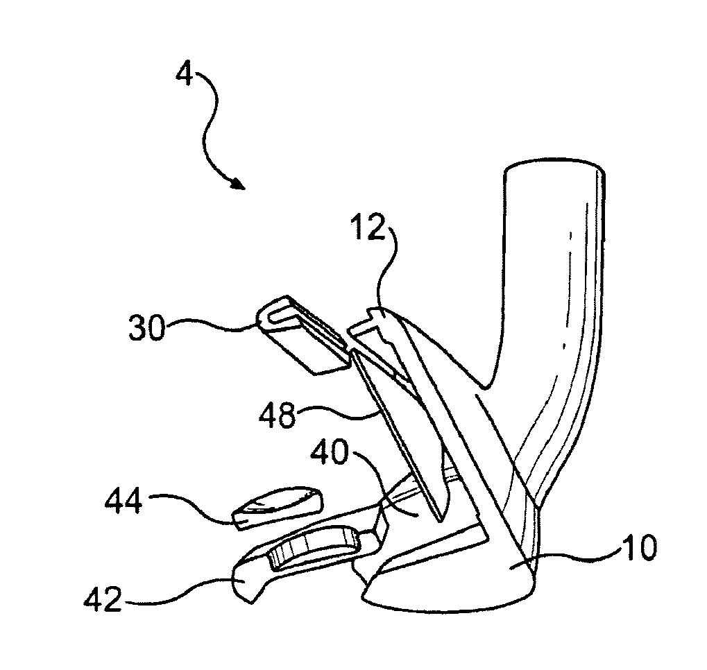
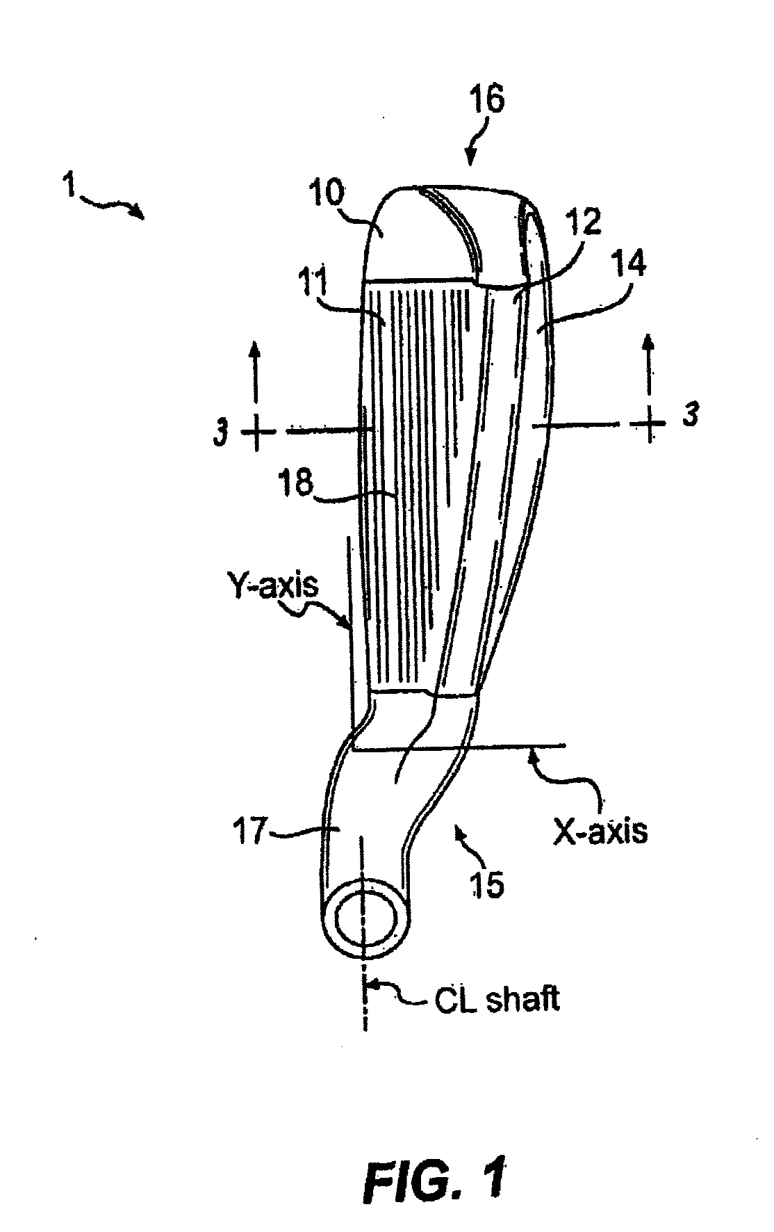
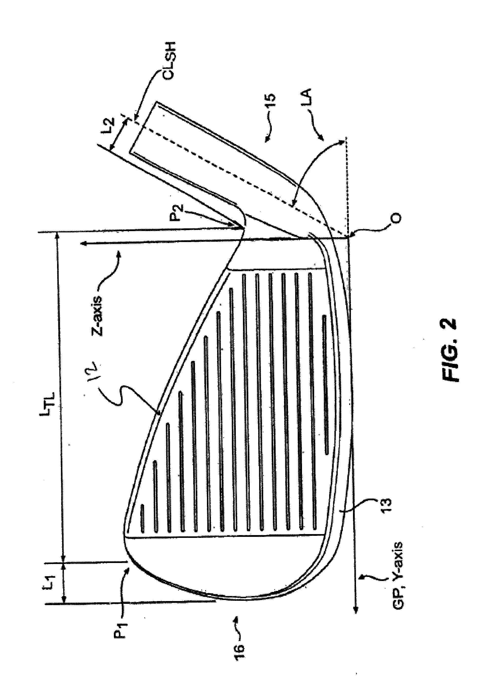
[0013]The present invention relates to a golf club head having a body defining a front surface, a top line, a sole, a back, a heel, a toe, and a hosel. The top portion of the club head, preferably the top line, contains a recess therein located between the heel and the toe, and extending toward the sole. Additional recesses, such as a toe recess and a heel recess, may also be provided in the top portion of the club head. In addition, the recess may extend along the top line from the heel around the toe of the top line. The use of such recesses remove material from the club head, allowing the opportunity to do one or more of the following: increase the size of the overall club head, expand the size of the club head sweet spot, lower the club head center of gravity, and / or produce a greater moment of inertia measured about a vertical or horizontal axis passing through the club head center of gravity. The golf club head of the present invention preferably is an iron-type, a utility-type, or a putter-type golf club head.
[0014]Inserts formed of a secondary material may be placed within the recesses. In one embodiment, these inserts have a density that is less than the density of the material used to form the club head body, and the inserts preferably are light-weight inserts. This allows the mass removed by the recesses to be replaced in more desirous locations on the club head, such as in the perimeter and / or toward the sole. The inserts may contain one or more dampening materials, such as a viscoelastic material, which have the added benefit of dissipating vibrations that may be created during the golf shot. Nylon is one example of a suitable insert material according to the invention. The incorporation of such dampening materials provides improved feel and improved weight distribution, enhancing performance of the club, while still maintaining an aesthetically pleasing overall head shape. The incorporation of the dampening materials also improves wearing of the heads over time since the viscoelastic material covers the top-toe area of the club, which is primarily responsible for marks on the head due to club-to-club impacts as the clubs rest in a player's bag.
[0015]In another aspect of the invention, the inserts extend to areas under the top line, thus allowing for the removal of even more mass from the top portion of the club head while permitting traditional methods of club head adjustment. For example, the lie and loft are typically adjusted using a device that clamps down on the top line. However, by setting some of the insert below the metallic top line, the clamp will not damage or disfigure the top line. The lightweight insert allows for mass to be removed from the top line and redistributed to other areas of the club to optimize center of gravity and moment of inertia, as well as expand the sweet spot of the club head.

Problems solved by technology

However, difficulty of use also increases with a decrease in loft angle and an increase in club length.
Because blade and muscle back designs have a small sweet spot, which is a term that refers to the area of the face that results in a desirable golf shot upon striking a golf ball, these designs are relatively difficult to wield and are typically only used by skilled golfers.
However, due to construction limitations or requirements, some of these designs inadvertently thicken the top portion of the club head.
However, this produces a club head with a bad aesthetic appearance.
However, there are disadvantages to reducing the hosel height, such as: reduced moment of inertia (since hosel mass is far away from the center of gravity); shaft-bonding concerns; and the inability to customize the club head via bending for loft / lie.
In addition, many golfers dislike the appearance of a club head that has a very small hosel.

Method used


Image

  • Golf club head wtih top line insert
  • Golf club head wtih top line insert
  • Golf club head wtih top line insert

Examples


Embodiment Construction

[0047]The present invention is directed to a golf club head with a top line insert. The top line insert may be fashioned in a variety of ways according to the invention. For example, in one embodiment, a recess and optional insert is located in the top line of the club head and extends along the top line. In another embodiment, the recess and optional insert extends around the toe of the club head. The insert may be formed of a variety of materials. For example, the insert may be lighter than the body of the club head to adjust the center of gravity downward. Alternatively, the insert may be heavier than the body of the club head to adjust the center of gravity upward. Each of the various embodiments are discussed in greater detail below and demonstrated with representative drawings.

[0048]The recess and optional insert may be used in a variety of club heads. For example, the club head may be a long iron, a short iron, or a set including both long and short irons where the recess and...


PUM


Abstract

A golf club head having a recess located in a top portion thereof between the heel and the toe and extending toward the sole. The recess may be only in the top line of the club head or extend from the heel around the toe. An insert may be placed within the recess. The insert may have a density that is less than the density of the club head body to lower the center of gravity and moment of inertia or greater than the density of the club head body to raise the center of gravity and moment of inertia.

Description

CROSS-REFERENCE TO RELATED APPLICATIONS[0001]This is a continuation-in-part of U.S. patent application Ser. No. 11 / 896,237, filed Aug. 30, 2007, now pending, which is a continuation-in-part of U.S. patent application Ser. No. 11 / 266,172, filed Nov. 4, 2005, now pending, which is a continuation-in-part of U.S. patent application Ser. No. 10 / 843,622, filed May 12, 2004, now pending, which are incorporated herein by reference in their entireties.FIELD OF THE INVENTION[0002]The present invention relates to a golf club, and, more particularly, to a golf club head having a top line recess with an insert. In particular, the golf club head of the present invention is directed to a design including a top line with a recess and an optional insert that extend along at least a portion of the top line around the toe. In addition, the present invention relates to a set of golf clubs with a recess and insert in the top line where the higher loft angle clubs have a heavier or higher specific gravit...

Claims


Application Information

Patent Timeline
Patent Type & Authority Applications(United States)
IPC IPC(8): A63B53/04
CPCA63B53/047A63B53/0487A63B59/0092A63B2053/0437A63B2053/0412A63B2053/0416A63B2053/0491A63B2053/0408A63B60/02A63B60/54A63B53/0408A63B53/0412A63B53/0416A63B53/0437A63B53/04A63B53/005
Inventor SORACCO, PETER L.ROACH, RYAN L.MORRIS, THOMAS C.
Owner COBRA GOLF
Learn More