
Pilot operated valve with fast closing poppet

a pilot-operated, valve technology, applied in the direction of fluid pressure control, instruments, servomotors, etc., can solve the problems of insufficient fast closing speed of an unbalanced valve when the electric current terminates, and the type of valve does not always provide the dynamic response required for some hydraulic systems,

Inactive Publication Date: 2009-08-27
HUSCO INT INC
View PDF11 Cites 45 Cited by
  • Summary
  • Abstract
  • Description
  • Claims
  • Application Information

AI Technical Summary

Benefits of technology

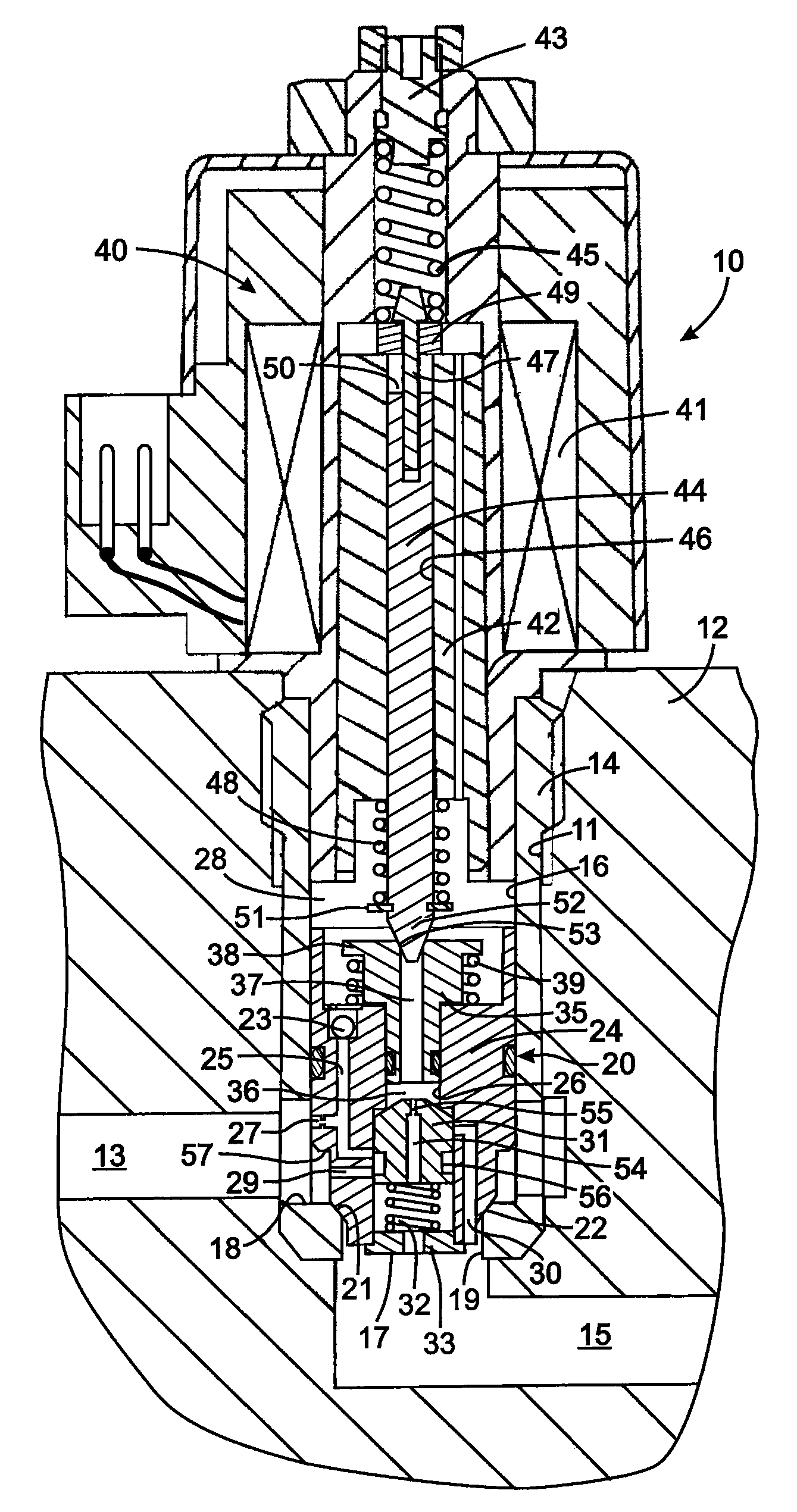
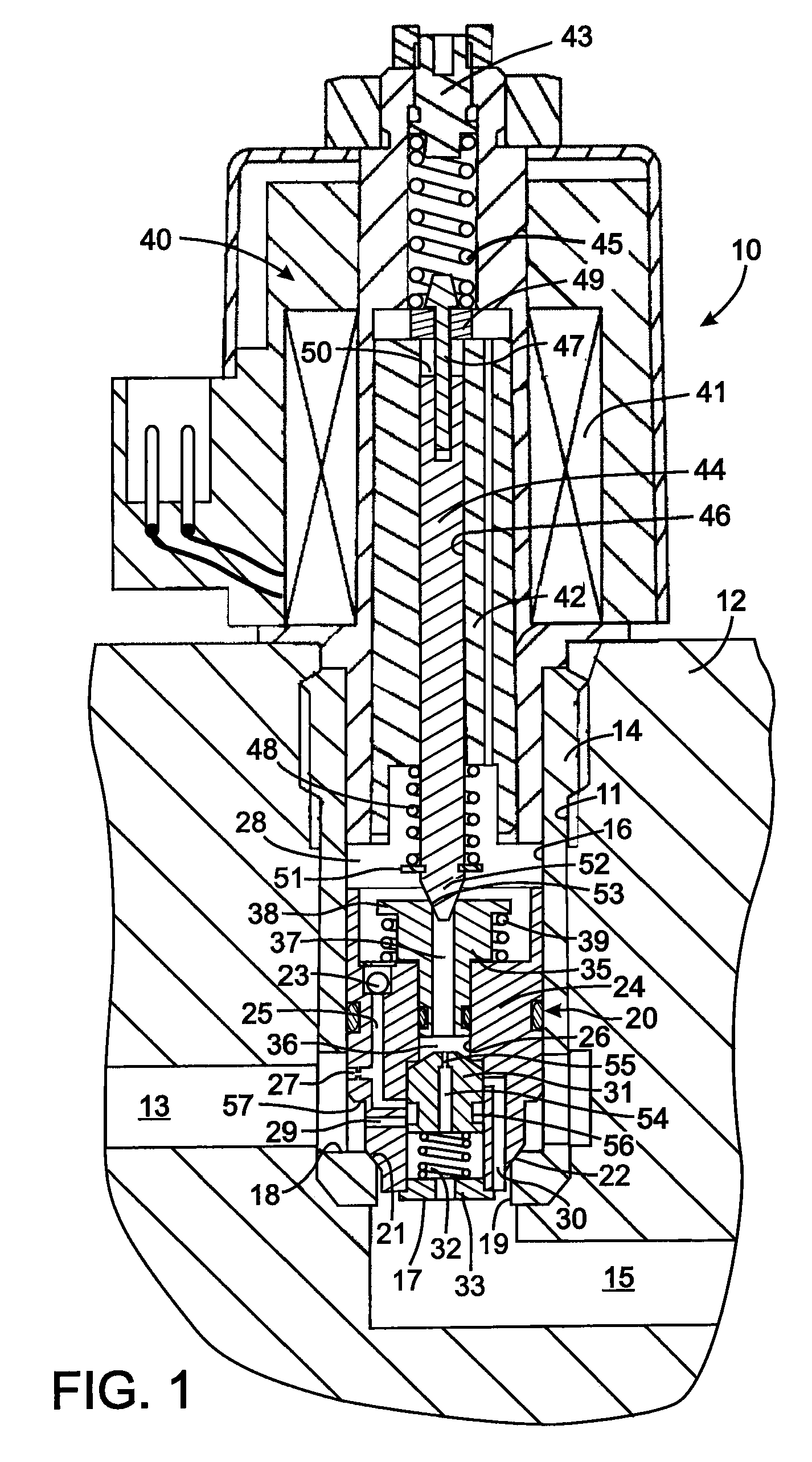
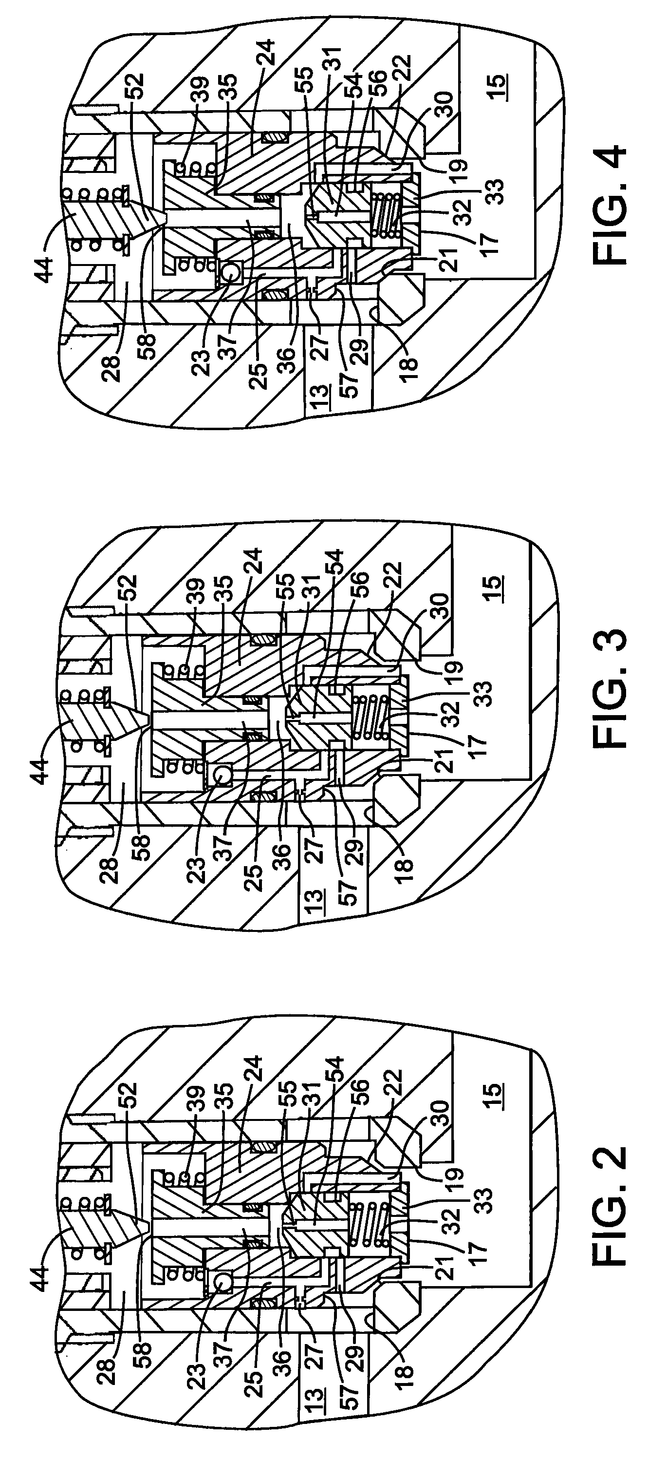
[0015]When the when valve is moving toward a more open position, the exhaust spool is in the second position wherein fluid flow from the first port into the control chamber is restricted by the orifice in the first control passage. That restriction enables proper modulation of the valve. When electric current is removed from the actuator to close the valve, the exhaust spool enters the first position and provides a path around the orifice, thereby enabling a greater fluid flow from the first port into the control chamber than in the second position.

Problems solved by technology

Nevertheless a pressure balanced valve of this type had durability, leakage, and pilot force sensitivities as compared to an unbalanced valve.
Although use of an unbalanced valve avoided those sensitivities, that type of valve did not always provide the dynamic response required for a some hydraulic systems, such as those for earth excavators.
Specifically the closing speed of an unbalanced valve when the electric current terminated often was not fast enough to properly control the associated hydraulic actuator.

Method used


Image

  • Pilot operated valve with fast closing poppet
  • Pilot operated valve with fast closing poppet
  • Pilot operated valve with fast closing poppet

Examples


Embodiment Construction

[0022]With reference to FIG. 1, a solenoid operated hydraulic valve 10 comprises a cylindrical valve body 14 that is mounted in an aperture 11 of a valve block 12. A first conduit 13 and a second conduit 15 in the valve block 12 open into the aperture 11. The valve body 14 has a longitudinal first bore 16 with a side wall through which, a first, or inlet, port 18 opens. A second, or outlet, port 19 opens into an end of the valve body's first bore 16 and communicates with the a second conduit 15 in the valve block. In one application of the hydraulic valve 10, the first conduit 13 is coupled to a hydraulic actuator and the second conduit 15 leads to the tank of the hydraulic system. A valve seat 21 is formed in the first bore 16 between the first and second ports 18 and 19.

[0023]A poppet assembly 20 comprises a main poppet 24, an exhaust spool 31, and a pilot piston 35. The main poppet 24 slides within the valve body's first bore 16 and selectively engages and disengages the valve se...


PUM


Abstract

A pilot-operated valve has a main poppet controlling fluid flow between inlet and outlet ports in response to pressure in a control chamber. Fluid flow through a pilot passage, linking the control chamber and the outlet port, moves an exhaust spool between first and second positions to control fluid flow through passages in the main poppet. The first position blocks flow between the control chamber and the outlet port and provides a path between the control chamber and the inlet port. In the second position, flow between the control chamber and the outlet port is enabled, and a second path, that is more restricted than the first path, is provided between the control chamber and the inlet port. When the valve closes, flow through the first path allows movement of the main poppet at a faster rate than during opening when flow occurs through the more restricted second path.

Description

CROSS-REFERENCE TO RELATED APPLICATIONS [0001]Not ApplicableSTATEMENT REGARDING FEDERALLY SPONSORED RESEARCH OR DEVELOPMENT [0002]Not ApplicableBACKGROUND OF THE INVENTION [0003]1. Field of the Invention[0004]The present invention relates to hydraulic valves, and more particularly to unbalanced, pilot-operated poppet valves.[0005]2. Description of the Related Art[0006]A wide variety of machines have moveable components which are operated by an hydraulic actuator, such as a cylinder and piston arrangement, that is controlled by a hydraulic valve assembly. A common hydraulic valve assembly comprises four electrohydraulic valves arranged in a Wheatstone bridge configuration with each valve in a different leg of the square bridge. One corner of the bridge is connected to a supply conduit, while the opposite corner of the bridge is connected to a tank return conduit. The other two corners are connected to the chambers of the hydraulic actuator. Opening two valves on opposite legs of the...

Claims


Application Information

Patent Timeline
IPC IPC(8): F16K31/12G05D16/20F16K31/40F15B13/04
CPCF15B11/006F15B13/0405F15B13/0433G05D7/0635F16K31/124F16K31/406F16K31/0648Y10T137/777Y10T137/5109G05D16/2097
Inventor PFAFF, JOSEPH L.SHIMELFARB, GENNADYLENTZ, CHRISTOPHER E.
Owner HUSCO INT INC
Learn More