
Space vector based synchronous modulating method and system

a synchronous modulation and space vector technology, applied in the field of vector modulation, can solve the problems of degrading performance, frustrating the purpose of synchronous modulation, complex calculation process, etc., and achieve the effect of reducing the number of calculation steps and making an angle of synchronous modulation more accura

Active Publication Date: 2011-05-12
ZHUZHOU CSR TIMES ELECTRIC CO LTD
View PDF26 Cites 5 Cited by
  • Summary
  • Abstract
  • Description
  • Claims
  • Application Information

AI Technical Summary

Benefits of technology

[0027]An object of the invention is to provide a synchronous modulation timing method based upon space vector modulation so as to reduce the number of calculation steps and make an angle of synchronous modulation more accurate.
[0055]The invention offer the following advantages over the prior art:
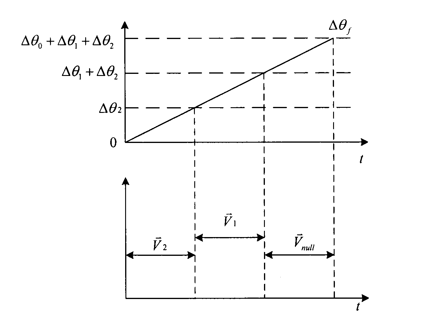
[0056]The invention calculates the output angles of the three fundamental voltage vectors of the reference voltage vector from the modulation angle θm of the reference voltage vector, the undergone Δθ and the modulation ratio m, compares the variation Δθf of the angle θ of the reference voltage vector with the output angles of the three fundamental voltage vectors and outputs the corresponding fundamental voltage vector in response to a comparison result. Directly with an angle reference, the invention calculates the output angles of the three fundamental voltage vectors and compares them with the angle variation for the purpose of outputting the corresponding fundamental voltage vectors to make a voltage output from the inverter consistent with the reference voltage vector. Due to the direct use of an angle reference, the invention can dispense with conversion of an angle into a period of time for calculation and reduce the number of calculation steps and can maintain accurately a synchronous modulation angle while the frequency f of the reference voltage varies dynamically.

Problems solved by technology

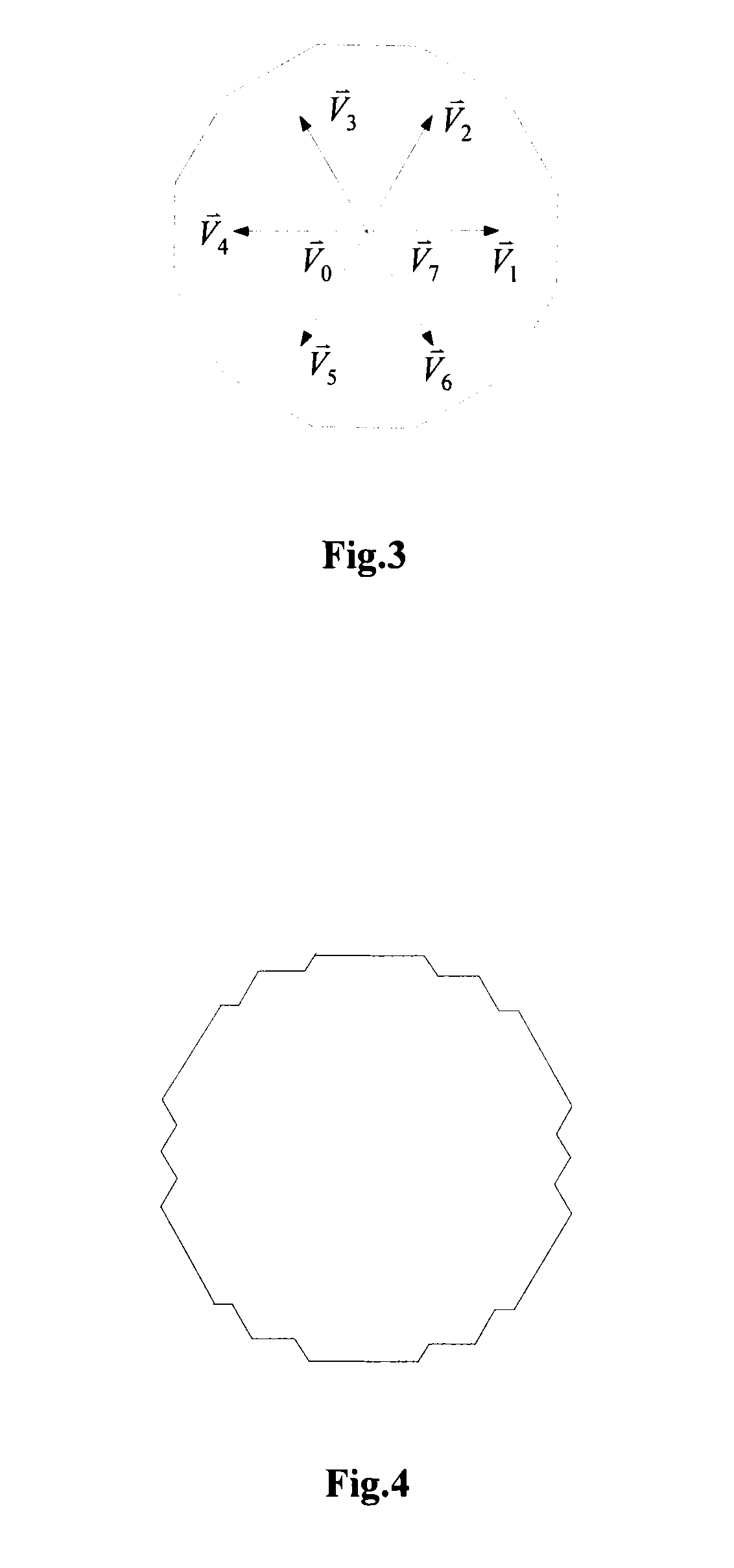
Ideally, it is desirable for the trace of the magnetic linkage to be a circle, but a voltage space vector is limited for the converter of a two-level voltage type, which makes it impossible for the magnetic linkage to be a circle, and consequently a circle has to be replaced with the most approximate polygonal to a circle.
Both of the methods have to convert an angle into a period of time for calculation and then provide a PWM output by means of a timer, which may result in a complex calculation process, and moreover a timing value is determined from the frequency of the modulation wave, but an input frequency may vary in the meantime, which may result in consistency of an actual PWM output angle with a predetermined angle, thus degrading the performance of and even frustrating the purpose of synchronous modulation.

Method used


Image

  • Space vector based synchronous modulating method and system
  • Space vector based synchronous modulating method and system
  • Space vector based synchronous modulating method and system

Examples


first embodiment

[0075]An embodiment of the method according to the invention will be detailed below with reference to FIG. 7 illustrating a flow chart of a space vector based synchronous modulation method according to the invention.

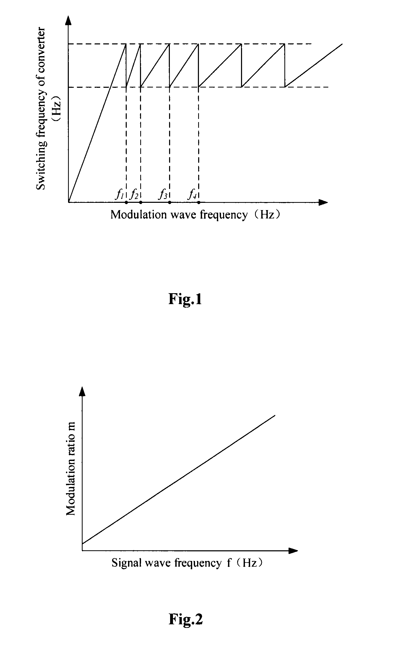
[0076]S701: The frequency f of a reference voltage vector is sampled, and a carrier wave ratio N is retrieved from a relationship table of frequencies and carrier wave ratios by using the frequency f.

[0077]S702: An angle Δθ that the reference voltage vector has undergone is derived from Δθ=2π / N, and a modulation angle θm of the reference voltage vector is derived from θm=(Nth−1)×Δθ, where Nth represents the Nth sampling, i.e., the Nth sampling of the reference voltage vector, and the number of times that it is sampled is N / 6 per sector. The angle Δθ that the reference voltage vector has undergone is an angle to be output from synchronous modulation.

[0078]S703: A modulation ratio m is retrieved from a modulation ratio vs. frequency graph.

[0079]S704: Output angles of three...

second embodiment

[0091]An embodiment of the method according to the invention will be detailed below with reference to FIG. 11. Reference is made to FIG. 11 illustrating a flow chart of a space vector based synchronous modulation method according to the invention. The method includes the following steps:

[0092]S1101: The frequency f of a reference voltage vector is sampled, and a carrier wave ratio N is retrieved from a relationship table of frequencies and carrier wave ratios by using the frequency f. The sampled frequency f of the reference voltage vector can be acquired in real time or at a predetermined interval of time.

[0093]S1102: An angle Δθ that the reference voltage vector has undergone is derived in Δθ=2π / N, and a modulation angle θm of the reference voltage vector is derived in θm=(N−1)×Δθ, where Nth represents the Nth sampling, i.e., the Nth sampling of the reference voltage vector, and the number of times that it is sampled is N / 6 per sector. The angle Δθ that the reference voltage vecto...


PUM


Abstract

A space vector based synchronous modulating method includes sampling a frequency f of a reference voltage vector; checking a relational table of frequencies and carrier wave ratios by the frequency f so as to obtain a carrier wave ratio N; obtaining a passing angle Δθ of the reference voltage vector by Δθ=2π / N; obtaining a modulating angle θm of the reference voltage vector by θm=(Nth−1)×Δθ, in which Nth indicates which time of sampling; obtaining a modulating ratio m according to a modulating ratio-frequency curve; accounting and synthesizing an output angle of three basic voltage vectors of the reference voltage vector according to the modulating angle θm and the passing angle Δθ of the reference voltage vector and the modulating ratio m; comparing a variable quantity θf the reference voltage vector angle θ and the output angle of three basic voltage vectors, and outputting corresponding basic voltage vectors according to the comparing result; synthesizing an output voltage in accordance with the reference voltage vector by the basic voltage vectors.

Description

PRIORITY CLAIM[0001]The present application is a National Phase entry of PCT Application No. PCT / CN2009 / 070448, filed Feb. 17, 2009, which claims priority to Chinese Patent Application no. 200810111288.4, filed with the Chinese Patent Office on Jun. 13, 2008 and entitled “Space vector synchronous modulation method and system”, the disclosures of which are hereby incorporated by reference in their entirety.FIELD OF THE INVENTION[0002]The present invention relates to the field of vector modulation and in particular to a vector space based synchronous modulation method.BACKGROUND OF THE INVENTION[0003]An alternating current (AC) drive system refers to a new drive system taking a motor as a control subject in which the speed and the torque of an AC motor is adjusted in a Variable Voltage Variable Frequency (VVVF) mode. The AC drive system is generally composed of a main circuit, a control system and a control subject, i.e., the AC motor. The main circuit includes a direct current (DC) b...

Claims


Application Information

Patent Timeline
IPC IPC(8): H04B17/00
CPCH02P27/12
Inventor DING, RONGJUNLI, JIANGHONGCHEN, GAOHUAXU, WEICHEN, HUAGUO
Owner ZHUZHOU CSR TIMES ELECTRIC CO LTD
Learn More