
Terrarium and related method of use

a technology of terrariums and terrariums, applied in the field of enclosures, can solve the problems of awkward user orientation and/or special tools, and the inability to reach the bottom of the terrarium, and achieve the effect of reducing the number of users and requiring special tools

Active Publication Date: 2017-09-07
CAPODICE MICHAEL W
View PDF3 Cites 6 Cited by
  • Summary
  • Abstract
  • Description
  • Claims
  • Application Information

AI Technical Summary

Benefits of technology

The patent text describes a new terrarium system that allows for easy ventilation, custom building, and modulation of heat and ventilation. The system includes an arcuate panel system that can slide and move without needing additional support. The system also includes modular support rings and accessories that allow users to custom build their own terrarium. The support column acts as a hidden conduit for electrical cords and other unsightly components. The arcuate panels can be shipped in a flat, manageable configuration. Overall, the new system offers improved ventilation and customization options for users and is easier to build and manage.

Problems solved by technology

This can be helpful, but in many cases, access to the interior from the top of the terrarium can be limited, particularly for tall-walled terrariums.
Reaching to the bottom of the terrarium, where most animal waste is disposed, can also be burdensome, requiring awkward user orientation and / or special tools.
While some manufacturers try to address these requirements, adding special fans and / or humidifiers, they usually fall short due to the size and shape of conventional enclosures.
Frequently, the add-ons also increase electricity consumption, and thus the cost of maintaining the terrarium.
Where the terrariums are large, the shipping can be expensive, and the packaging for the same can be overly bulky and unwieldy.
Frequently, the electrical cord is left unconcealed, which can be unsightly and can present safety issues.
These items, however, can be unwieldy and difficult to secure, particularly where they are self-supporting or leaned into the corners of the walls.

Method used


Image

  • Terrarium and related method of use
  • Terrarium and related method of use
  • Terrarium and related method of use

Examples


Embodiment Construction

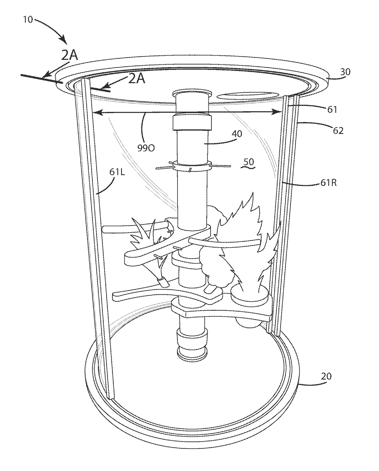
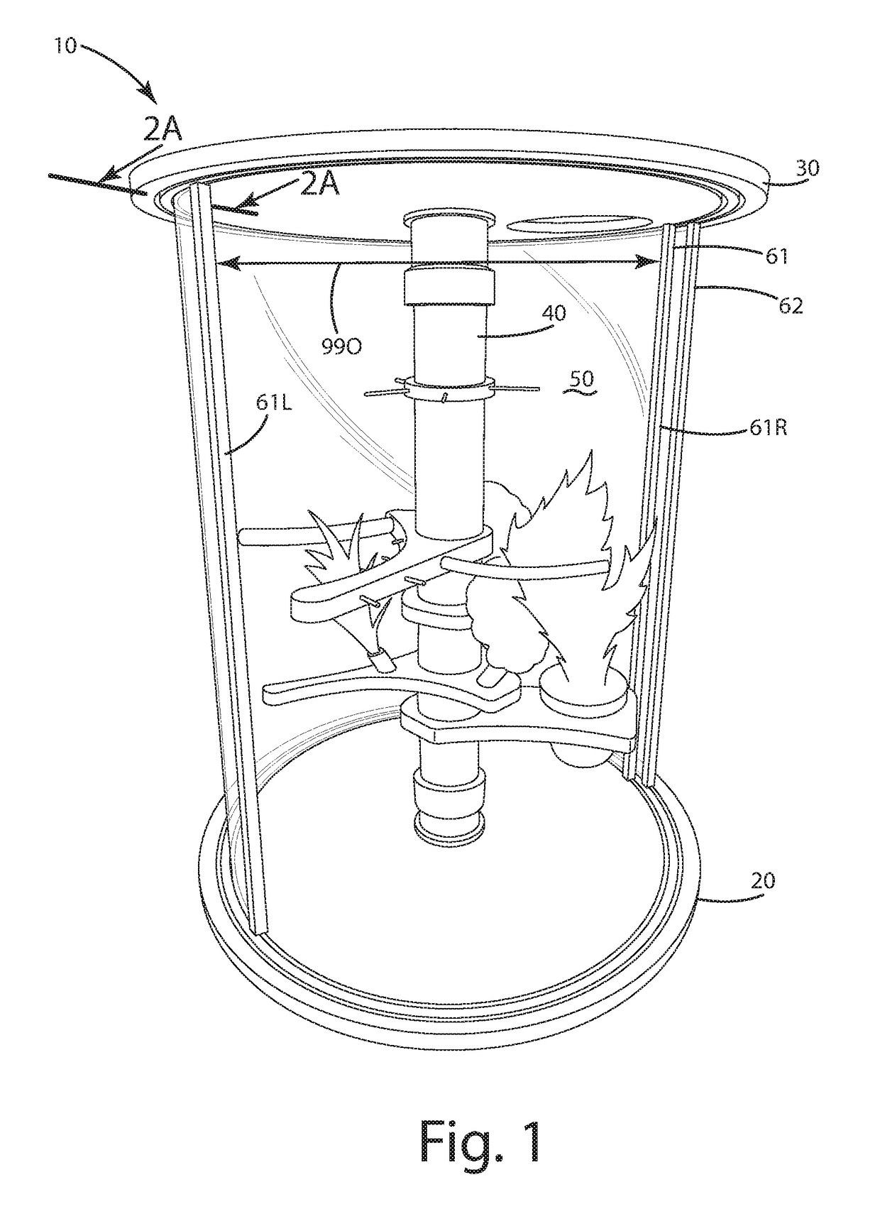
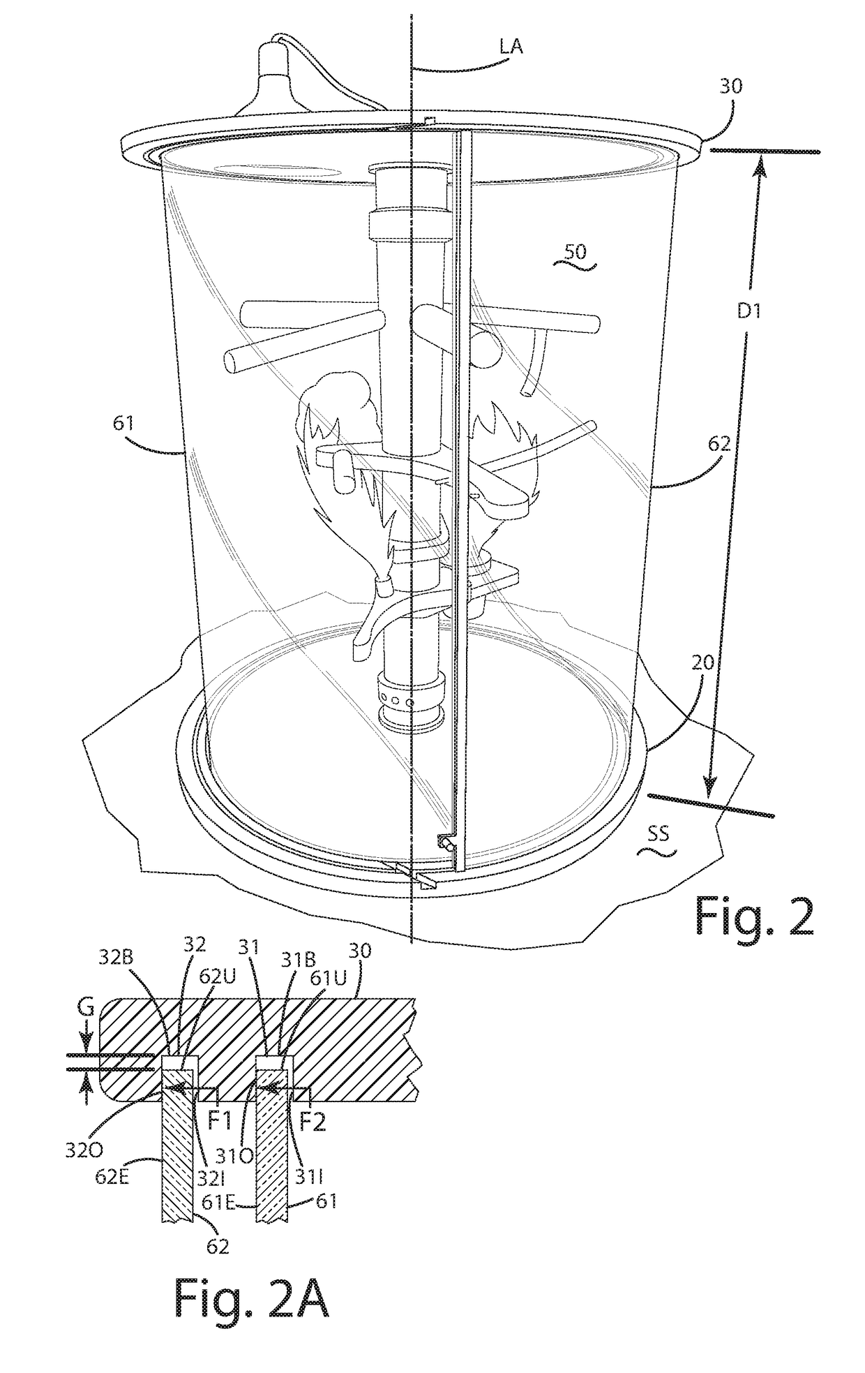
[0056]A current embodiment of the terrarium is illustrated in FIGS. 1-21, and generally designated 10. The terrarium can include a base 20, a top 30 and a support column 40. The support column can be configured to define an interior bore 43 that extends from a first or lower end 41 to a second or upper and 42. The interior bore 43 can form a chimney within the confines of the terrarium. This chimney can provide ventilation and can circulate air within the internal compartment 50 of the terrarium via a system of one or more vents, for example lower and upper vents 41V and 42V. The support column 40 also can be constructed so that it substantially entirely supports the top 30 relative to the base 20, holding the top a first preselected distance D1 therefrom. The support column can support optionally 95%-100% of the weight of the top 30, while the one or more arcuate panels 61 and 62 optionally can support 5%-0% of the weight of the top 30.

[0057]The arcuate panels themselves can be con...


PUM


Abstract

A terrarium including a base, a support column, a top, and one or more arcuate panels with a closure is provided. The base can include one or more base channels, and the top can include one or more top channels. The top can be supported entirely by the support column at a first preselected distance from the base. One or more arcuate panels can extend between the top and the base, being disposed in the top channel and the base channel, and forming an opening. Another arcuate panel can form a closure over the opening, with that panel optionally slidable to selectively access an internal compartment of the terrarium. The support column can support the top and assist in holding the arcuate panels, as well as form a ventilation chimney associated with the internal compartment. Related methods of use are provided.

Description

BACKGROUND OF THE INVENTION[0001]The present invention relates to enclosures, and more particularly to a terrarium for housing plants and / or animals, and a related method of use.[0002]There are a variety of terrariums used to house and keep animals, such as reptiles, amphibians and fish, as well as other animals, and plants. Conventional terrariums are constructed to include transparent glass so that users can observe the animals or plants from outside the terrarium. Many terrariums are constructed in the form of a box or rectangular shape for simplicity. For example, some are formed from four glass walls arranged perpendicular to one another to form a box shape. The walls are fastened to a bottom and a rectangular cover rests atop the walls to prevent the animals from escaping. The cover typically is fully supported by the walls, and is removable to access the interior of the terrarium for routine maintenance and cleaning. This can be helpful, but in many cases, access to the inter...

Claims


Application Information

Patent Timeline
Patent Type & Authority Applications(United States)
IPC IPC(8): A01K63/00A01G27/00A01G9/20A01G9/02
CPCA01K63/006A01G9/20A01G27/00A01G9/02A01G9/16
Inventor CAPODICE, MICHAEL W.
Owner CAPODICE MICHAEL W
Learn More