
Sawing apparatus and method for using a sawing apparatus

Inactive Publication Date: 2009-08-27
LINEARTEC
View PDF2 Cites 7 Cited by
  • Summary
  • Abstract
  • Description
  • Claims
  • Application Information

AI Technical Summary

Benefits of technology

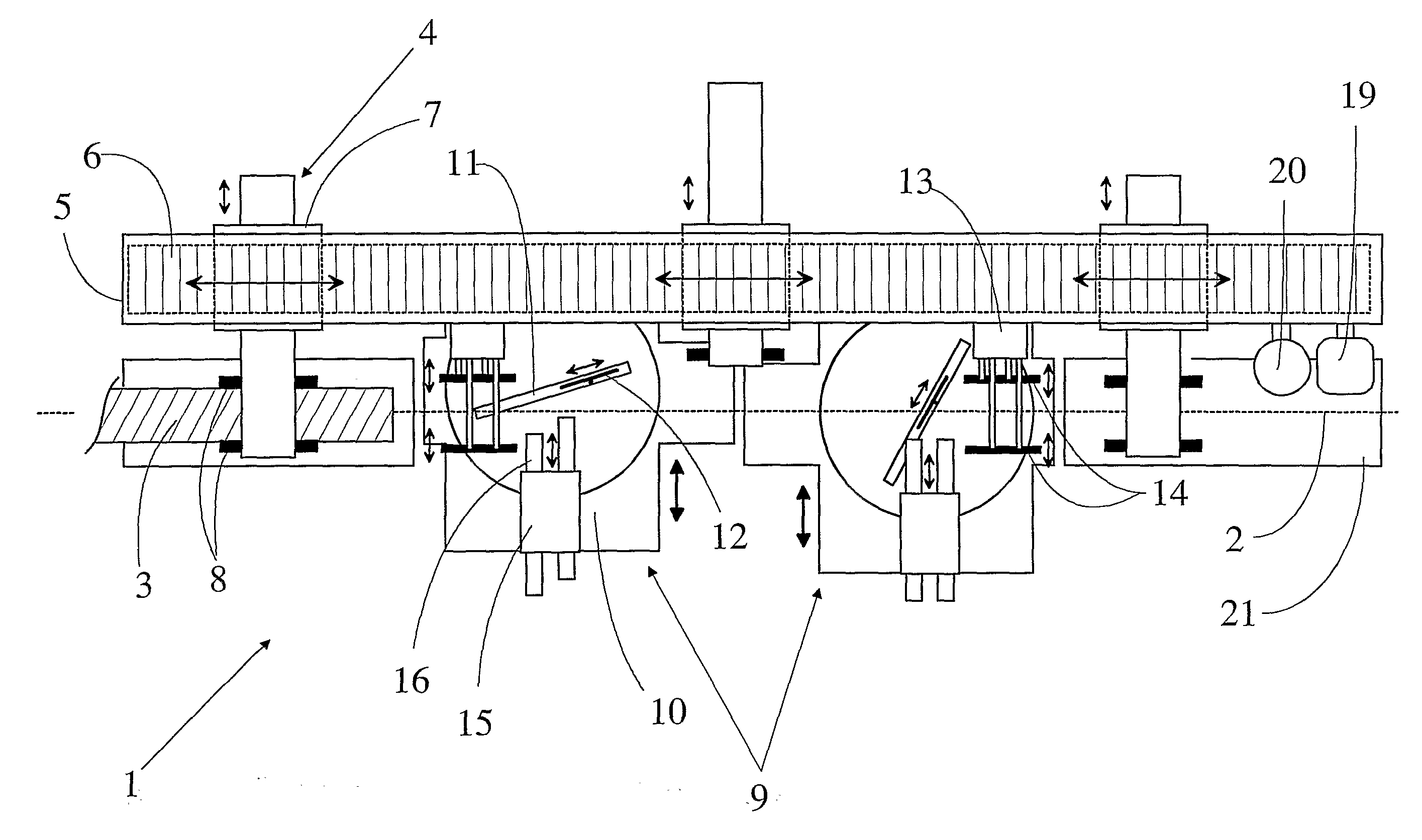
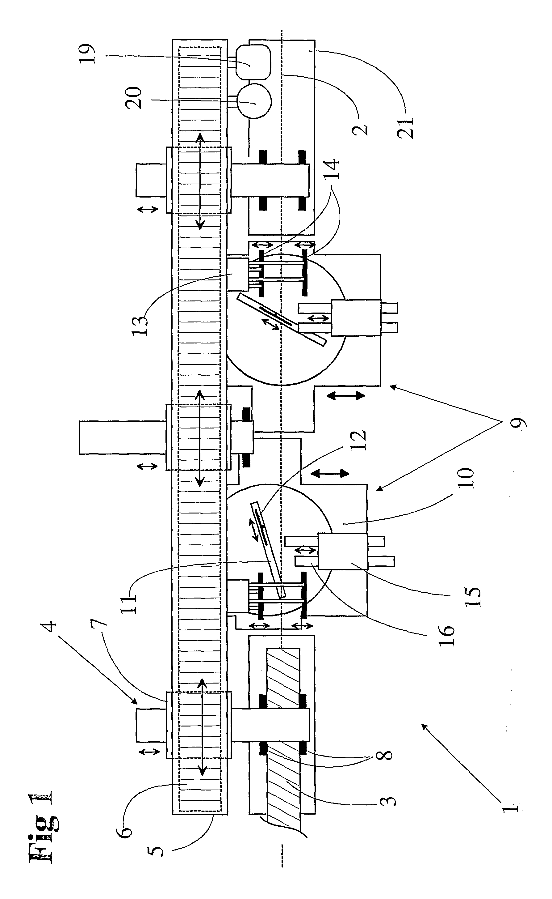
[0011]According to the invention, the transfer means include an elongated magnetic rail parallel to the processing line, as well as at least two slides of a linear motor, arranged to be movable independently with respect to one another along the aforementioned magnetic rail. Each linear motor slide forms an electric linear motor together with the magnetic rail. For guiding and limiting the movement of the slide which moves on the rail at a distance of an air slot from the magnetic rail, the apparatus can naturally also include various linear guides. Each slide includes, in addition, a transfer gripper connected to the slide and arranged to grasp the timber for transferring it longitudinally along the processing line. Several transfer grippers connected independent of each other to the slides being guided and movable using direct linear drive enable the use of a sawing apparatus that is very efficient and can be flexibly adapted to various production situations. One can, for example, transfer a piece being machined into position for machining using a first transfer gripper and after the machining phase use a second gripper for the further transfer, whereby the first gripper is released to pick up the following piece. For purposes of grasping the timber, the transfer grippers can include, for example, two opposite gripper parts that move crosswise with respect to the processing line for grasping the timber by tightening it between the gripping surfaces. The magnetic rail and the movement range of the slides on the rail preferably extend over the entire length of the apparatus and more preferably even beyond it, whereby no separate conveyors are needed for feeding the timber to and from the apparatus. The use of a linear motor which is to be guided automatically, e.g. using servo control, enables very high acceleration and speed of the timber being transferred, as well as excellent positioning accuracy. A linear motor also avoids the flexibility and lost motions associated with mechanical transmission. Furthermore, the linear motor slides that move in a substantially frictionless manner on the magnetic rail considerably reduce the need for maintenance caused by the wear of the parts. Of the structures of the processing line, the separate transfer grippers enable a very simple structure of the processing line.
[0035]Two saws and a method for their simultaneous use as well as separate transfer means and holding means also enhance making the timber to form cut-to-size pieces. The efficiency is also enhanced by a sawing method which minimises the time-consuming saw movements during the actual sawing phase. Besides saws, it is possible to connect to the apparatus also other necessary machining means such as a milling cutter and a drill. The apparatus can be integrated to form a fully automatic part of the rest of the production line that can be controlled using the production control system of the plant. The invention is very well applicable to the manufacture of roof trusses or similar parts that contain a lot of bevels of different directions. It can also be used in the manufacture of logs. It is also very versatile and is not limited to the aforementioned embodiments.

Problems solved by technology

Due their complicated and costly mechanical structure, these are very susceptible to wear or problems caused by wood dust, which increases the need for maintenance and costs associated with maintenance.
Furthermore, particularly the conveyance of timber which is carried out using various roller conveyors is very inaccurate, resulting in multiplied sawing inaccuracies when the same piece is sawed a number of times and moved in the meanwhile.
Another alternative is to make a re-measurement prior to every work phase, which can also result in big measurement inaccuracies in the final product.
A conveyor that is based on rollers rolling under the timber includes quite a large number of parts that wear and requires a lot of maintenance to maintain the operation thereof.
As the horizontal possibility of movement is lacking, the presented solution cannot be used to implement very long sawing lines.
On the basis of the facts described above, the presented apparatus does not meet the requirements of large-scale industrial production, but is better suitable for small-scale operations.
Moving an entire saw unit to a distance each time required by the length of the part being sawed is a cumbersome and time-consuming procedure, and the mechanism required by it also increases the need for maintenance.
As a whole, this apparatus is not designed either to be integrated into an efficient fully automated production system.
Furthermore, the apparatus is specifically designed for cutting rather lightweight strips.
Consequently, the solution is not very useful in manufacturing, for example, parts of a roof truss that are typically rather heavy, of unequal length and include different bevels.

Method used


Image

  • Sawing apparatus and method for using a sawing apparatus
  • Sawing apparatus and method for using a sawing apparatus
  • Sawing apparatus and method for using a sawing apparatus

Examples


Embodiment Construction

[0039]The sawing apparatus 1 of FIG. 1 has a processing line 2 whose centre line is shown in the figure with a dotted line. The ends of the processing line have supporting planes 21 for supporting the timber 3.

[0040]Supported on the frame 5 (of which just a part is shown in the figure for the sake of clarity) of the sawing apparatus, in parallel to the processing line, aside from it and above it, is a magnetic rail 6 comprising consecutive permanent magnets. Three linear motor slides 7 have been arranged to be movable along the magnetic rail beneath it. Connected to each slide is a transfer gripper 4. For supporting the slides and for controlling their movement, the sides of the magnetic rail are provided with linear guides (not shown in the figure) connected to the apparatus frame, and the slides move along them. The slides can be moved along the magnetic rail independently with respect to one another. The transfer grippers have been arranged to be movable in the horizontal directi...


PUM


Abstract

A sawing apparatus (1) for cutting elongated timber (3) to form cut-to-size pieces, the apparatus including a horizontal processing line (2), through which the timber being processed is guided; transfer means for transferring the timber longitudinally along the processing line as well as machining means for machining the timber in the processing line. The machining means include at least one circular saw (9) whose sawing angle is adjustable and whose blade can be moved across the processing line for cutting the timber. According to the invention, the transfer means include an elongated magnetic rail (6) parallel to the processing line (2); at least two linear motor slides (7) arranged to be movable independently with respect to one another along the magnetic rail; and for each linear motor slide, a transfer gripper (4) connected to the slide and arranged to grasp the timber being processed for moving it longitudinally along the processing line.

Description

FIELD OF THE INVENTION[0001]The invention relates to a sawing apparatus as defined in the preamble of claim 1 for cutting elongated timber to cut-to-size pieces as well as to a method as defined in the preamble of claim 12 for using a sawing apparatus.BACKGROUND OF THE INVENTION[0002]The parts of various wooden structures, such as those of roof trusses or, for example, those of timber walls need to be machined to form cut-to-size pieces prior to the manufacture of the structure. Besides cutting to size, for example, the ends of parts of roof trusses or similar shall typically also be provided with bevels of different directions to join the parts against one another at different angles. The directions of the bevels or bevel combinations, as well as also the lengths of the usually elongated components have to be implemented so as to have high dimensional accuracy to make the joints of the components sufficiently durable. In addition to the accuracy, the production shall be sufficientl...

Claims


Application Information

Patent Timeline
IPC IPC(8): B27B1/00B27M1/08B27BB27B29/00B27B29/08B27B31/00B65G54/02
CPCB27B29/00B27B29/08B65G2201/0282B65G54/02B27B31/00
Inventor NUUTINEN, ARVO
Owner LINEARTEC
Learn More