
System for detecting vehicles

a technology for detecting systems and vehicles, applied in the field of systems for detecting vehicles, can solve the problems of frequent false alarms, high maintenance costs, and poor scene luminance,

Active Publication Date: 2009-08-20
KRIA
View PDF5 Cites 70 Cited by
  • Summary
  • Abstract
  • Description
  • Claims
  • Application Information

AI Technical Summary

Benefits of technology

"The present invention is a detection system that overcomes the limitations of current technologies. It uses multi-spectrum video cameras and license plate reading procedures to detect and document infringements, identifying the vehicle's owner. The system is reliable, can detect rapid violations, operates in poor lighting conditions, and is protected against vandalism. It is also cost-effective and easy to install. The technical effects of the invention are improved detection results and more detailed documentation of the event, while eliminating safety risks and the risk of the installation being tampered with."

Problems solved by technology

Transits are usually detected by sensors of the presence of a vehicle (inductive loops, lasers, radar, etc.), all devices whose installation in general requires road traffic to be halted and whose operation involves expensive maintenance.
It is also known that video detection based on simple movement (motion detection and / or the so-called “virtual loops”) is subject to frequent false alarms in the absence of other observations that confirm detection.
However, much more light is often reflected from the license plate than from the bodywork of the vehicle, thus the dynamic range of the scene luminance is too wide for the video camera's capabilities (whether it employs photographic film or is of the digital type) to enable both the license plate area and the model and colour of the vehicle to be recognisable at the same time, with the effect of producing documentation that cannot be used for the purpose of disciplinary proceedings.
An evident and specific limitation of analog cameras lies in the limited length of the roll of film, that is the small number of photographs that can be taken; this requires personnel to visit the installation frequently to replace the film manually and develop it, after which if appropriate the images are acquired by a scanner for filing purposes.
Digital cameras are beginning to replace those employing photographic film, partially reducing these drawbacks; however, they share with analog cameras the limitations due to wear on moving parts (shutter, diaphragm).
Furthermore, all systems that use cameras are unable to document violations that take place in rapid succession; for example they are not capable of documenting the frequent cases in which a first infringing vehicle in transit is immediately followed by others, with an overlap in time between the end of one vehicle violation and the start of the subsequent vehicle.
Some systems based on video cameras (thus with continuous image acquisition) have a more evident limit when operating in conditions of poor illumination, in particular with regard to the legibility of the license plate.
For example, sudden lighting of the flash is frequently contested since it is held to be potentially dangerous for the associated risk of dazzling: even if the system photographs the “detected” vehicle from behind, a driver proceeding in the opposite direction to that controlled might be dazzled by it.
Again, in view of their current use being chiefly disciplinary, detection systems are exposed to acts of vandalism: this also due to the fact that such systems are not normally supervised.
Typical acts of tampering consist in deactivating the detection sensors and blacking out (or blinding) the image-acquisition devices.

Method used


Image

  • System for detecting vehicles
  • System for detecting vehicles
  • System for detecting vehicles

Examples


Embodiment Construction

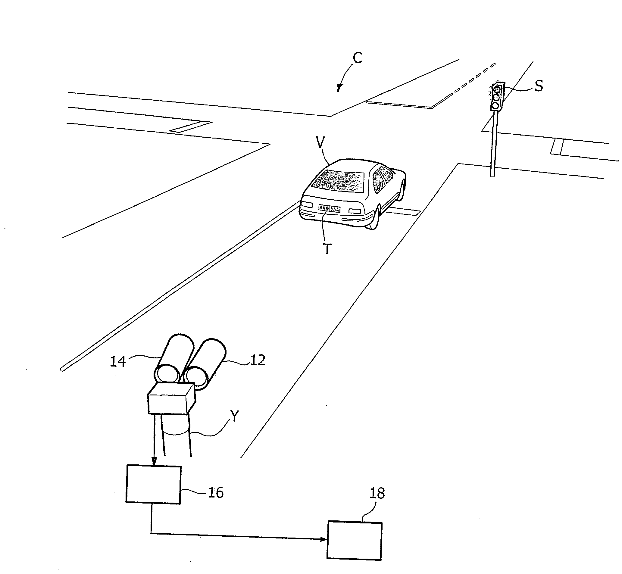
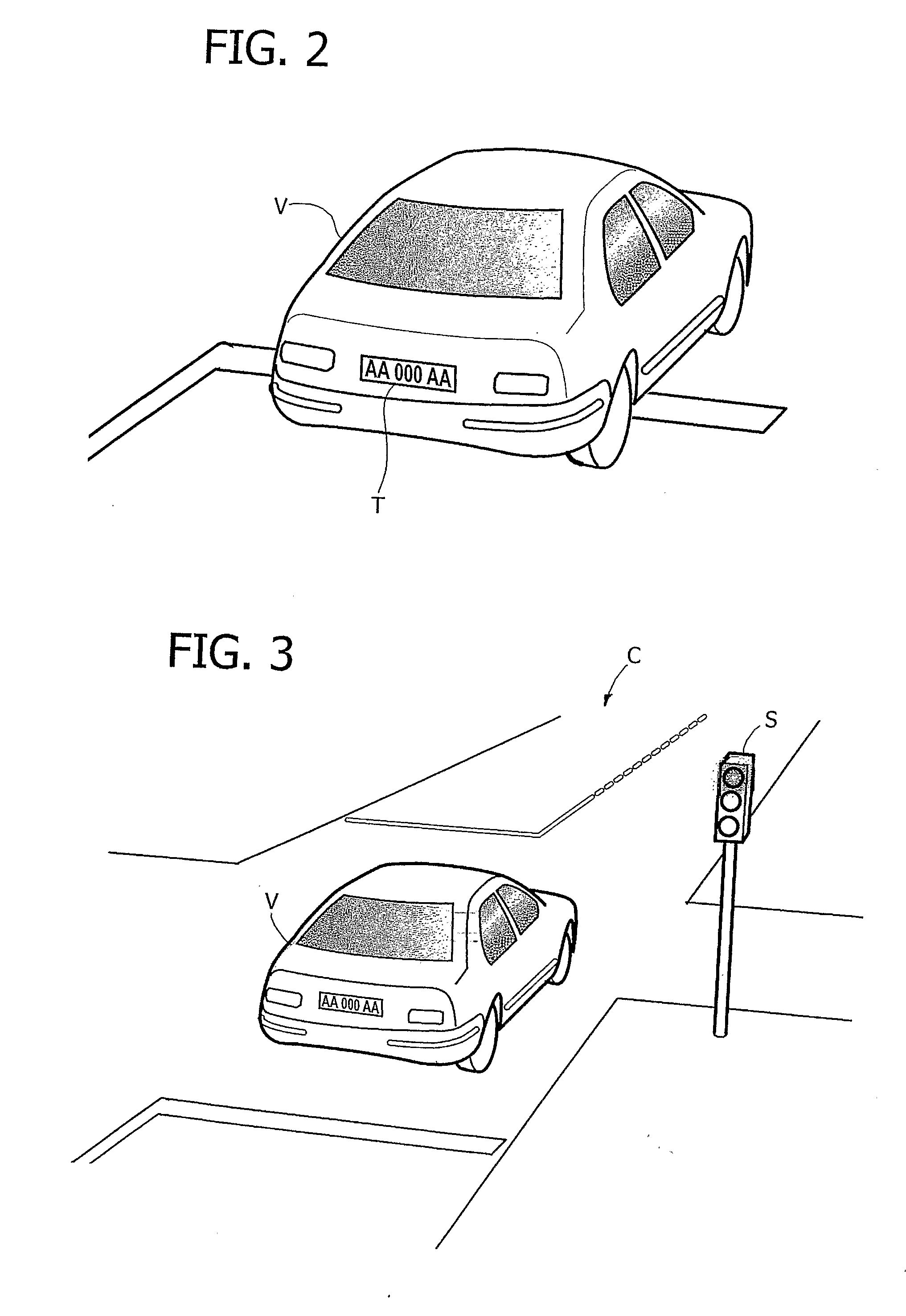
[0036]The following detailed description relates, by way of example, to the possible use of a system of the type described in correspondence with a road intersection C served by traffic lights of which one of the traffic lights S is visible. This is in order to detect infringements of the traffic law essentially relating to:[0037]failure to stop at the intersection when the traffic lights are red, and / or[0038]exceeding a speed limit.

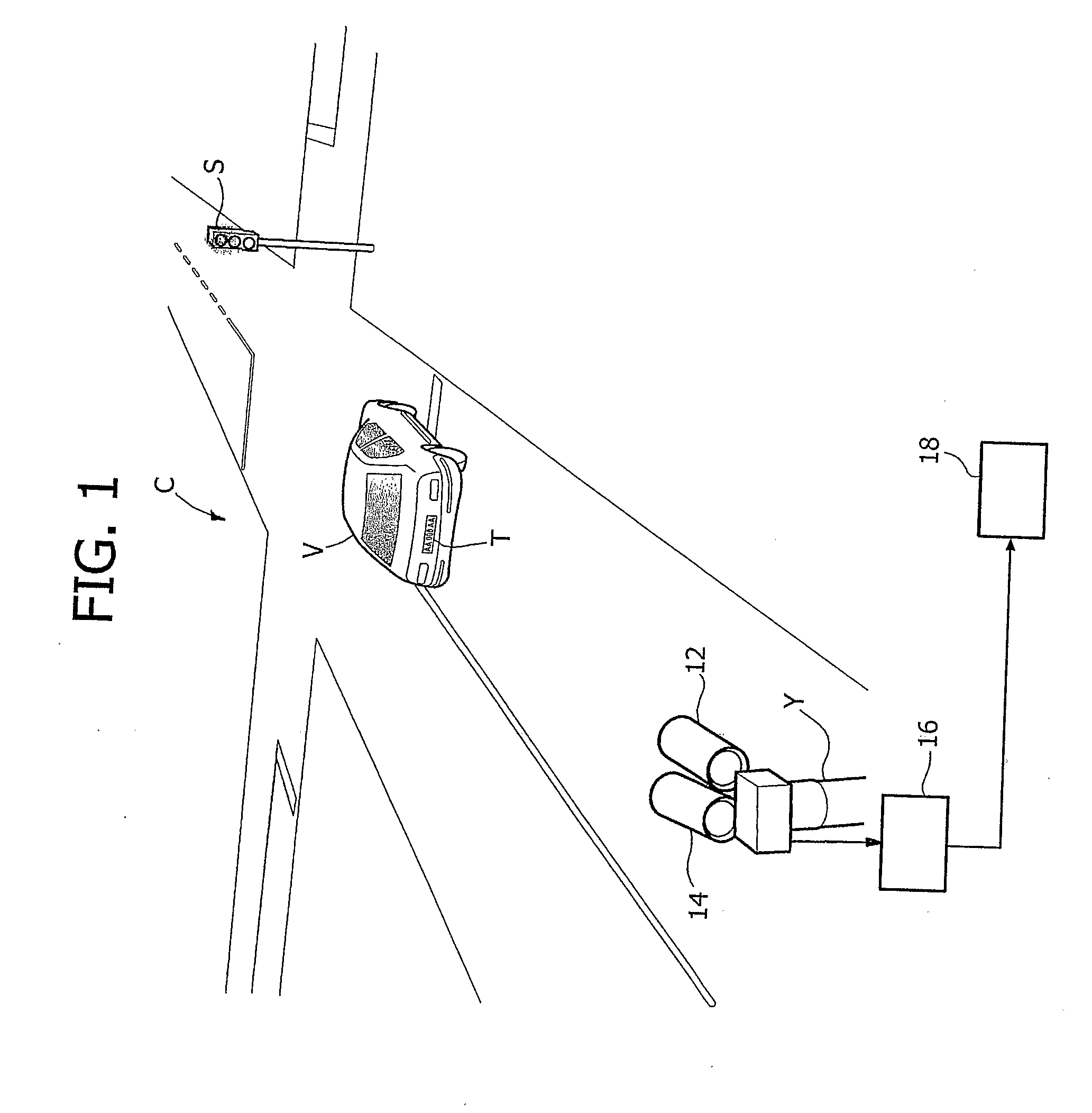
[0039]In the configuration to which FIG. 1 relates, the system (indicated overall with 10 in the diagram in FIG. 4) comprises a plurality of installations installed on a pole Y and including a pair of video cameras 12, 14 (for preference the first infrared and the second colour) linked to a processing unit 16 (shown in FIG. 1 as situated in the neighbourhood of the video camera), in its turn communicating with a central unit 18, in general at a remote control centre.

[0040]Connections among the video cameras 12 and 14, the processing unit 16 (or the vario...


PUM


Abstract

A system to detect the transit of vehicles having license plates includes at least one video camera to detect license plates capable of framing the plates of said vehicles and, preferably, at least one video camera to detect vehicles capable of framing a zone of transit of said vehicles having license plates. A series of processing operations is capable, starting from the video signals generated by the video camera to detect license plates, of detecting the presence of a vehicle in transit and, starting from the video signals generated by the video camera to detect vehicles, of detecting the position and three-dimensional shape of vehicles in transit in said zone. A supervisor module aggregates the results of these processing operations to generate records of information each identifying the modality of transit in said zone of a vehicle identified by a given license plate that has been recognized.

Description

FIELD OF THE INVENTION[0001]The invention relates to systems for detecting vehicles and has been developed with particular attention to its possible use in detecting violations of traffic regulations, for example failure to stop at red traffic lights, exceeding speed limits, unauthorised overtaking and access.DESCRIPTION OF THE KNOWN TECHNOLOGY[0002]Systems for automatically identifying vehicles that infringe traffic regulations must respond to the requirements of reliably detecting the violation and producing clear documentation; they must also guarantee drivers' safety and be difficult to tamper with.[0003]Existing systems generally comprise detection sensors linked to cameras that, for example, take sequences of two still photographs to demonstrate the movement of the vehicle committing the violation.[0004]Transits are usually detected by sensors of the presence of a vehicle (inductive loops, lasers, radar, etc.), all devices whose installation in general requires road traffic to...

Claims


Application Information

Patent Timeline
Patent Type & Authority Applications(United States)
IPC IPC(8): G08G1/017G08G1/04G08G1/054
CPCG06K9/3258G08G1/054G08G1/04G08G1/0175G06V20/63
Inventor ARRIGHETTI, STEFANO
Owner KRIA
Learn More